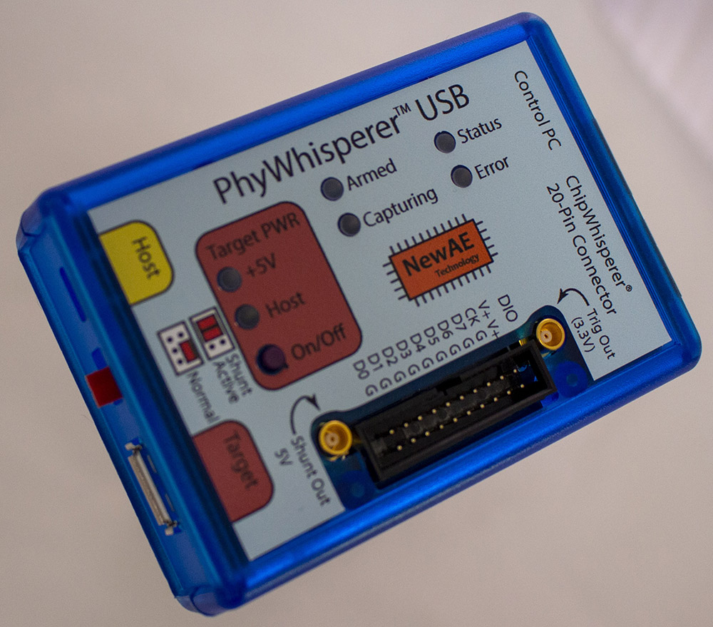
PhyWhisperer-USB
The PhyWhisperer is a trigger for fault injection or side channel analysis which triggers on the USB PHY. It's also capable of performing basic USB sniffing.
Software Docs/Installation
https://phywhispererusb.readthedocs.io/en/latest/
Features
- Full USB 2.0 (LS/FS/HS) support
- Low latency hardware triggering on USB data
- Can generate USB synchronized clock signal, allowing very repeatable power measurements
- Easy connection to other NewAE (ChipWhisperer, ChipSHOUTER) and non-NewAE (GreatFET, oscilloscope) products
- Hardware sniffing, including error detection and cycle accurate timestamps
- Programmable cycle accurate offset for trigger
- Easy to use Python API
- Fully open source, plus spare room on FPGA means you can extend its functionality
- Built in shunt resistor for power analysis
- Requires external measurement tool (ChipWhisperer, oscilloscope)
- Target power control for easy resets when glitching
- Target power control via Python API and via button on device
Specifications
| Feature | Notes/Range |
|---|---|
| USB modes supported | USB 2.0 Low/Full/High Speed |
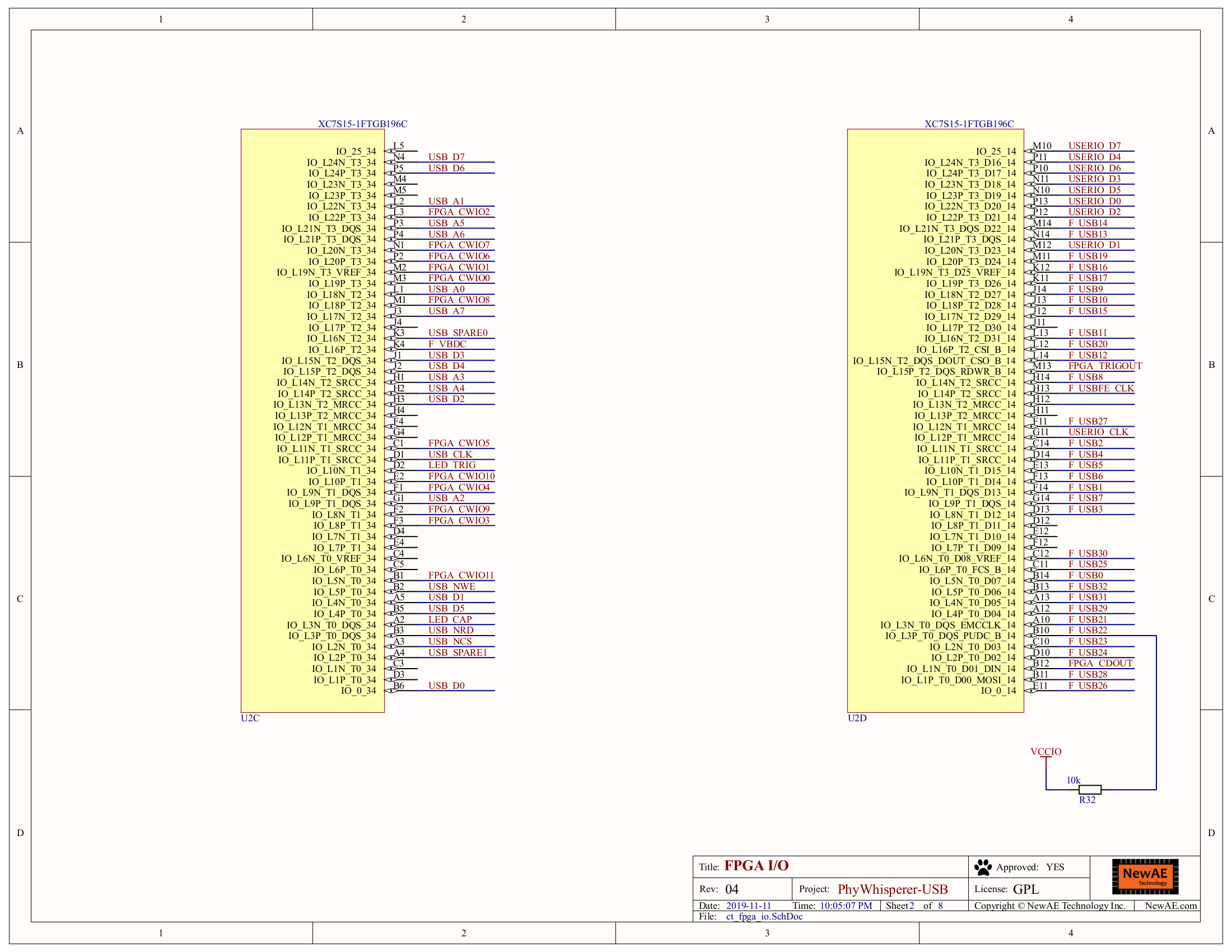
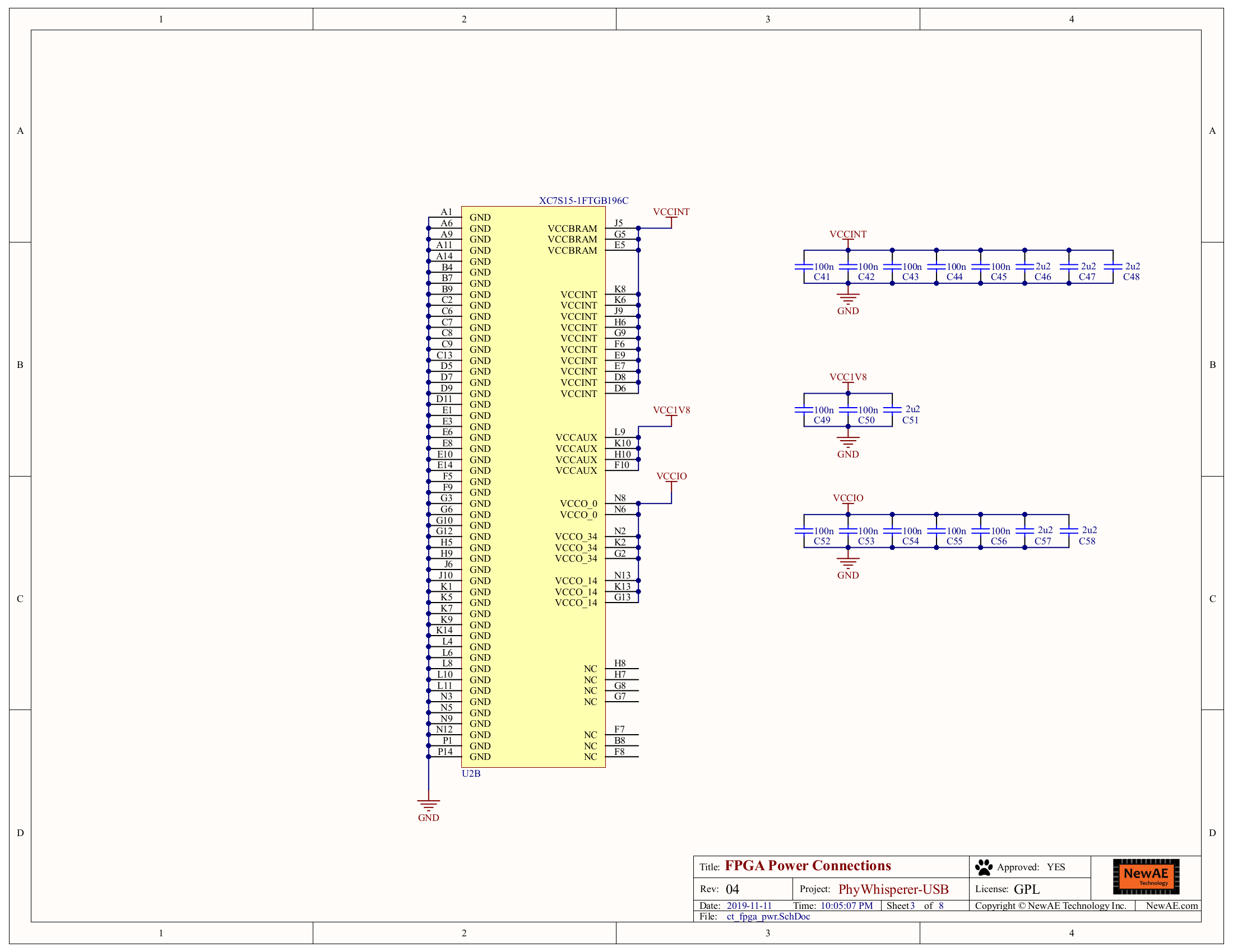
| FPGA | Xilinx Spartan 7S15 |
| Control PC Connection | Micro-USB 2.0 HS |
| Host USB connection | Micro-USB |
| Target USB connection | Female A Connector |
| Target power source | Host USB or Control PC |
| Spare Digital I/O | 8 data pins, 1 clock pin |
| Clock output | 60MHz, derived from 480MHz USB clock |
| Trigger pattern | 1-64 bytes with mask |
| Trigger delay | 0-1048576 cycles of 240MHz internal clock (derived from USB clock) |
| USB sniffer FIFO | 8192 bytes (FPGA RAM) |
| Control PC Software | Python 3 library, Windows/Mac/Linux support, signed Windows drivers |
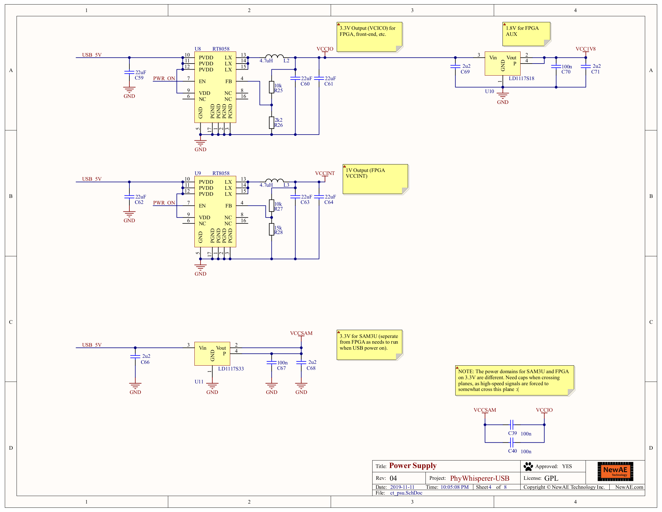
| Shunt Resistor | 5Ω, bypassable via jumper |
| Enclosure | Yes (not waterproof) |
USB Control
| Feature | Notes/Range |
|---|---|
| USB | USB 2.0 High Speed |
| VendorID | 0x2B3E |
| ProductID | 0xC610 |
| Interfaces | Vendor |
| WCID (Windows 10 automatic driver installation) | ✅ (firmware >= 1.1) |
Controlling the PhyWhisperer
Similar to the ChipWhisperer platform, the PhyWhisperer can be controlled via a Python API. The API has its own ReadTheDocs page: https://phywhispererusb.readthedocs.io/en/latest/. This page also documents the software install process, including driver installation.
The PhyWhisperer Github page also has a few example Jupyter notebooks showcasing the Python API, located in software/jupyter/.
Reprogramming the PhyWhisperer
Both the FPGA and SAM3U have debug headers accessible on the PCB, as well as ROM resident bootloaders, accessible over USB. Usage of the ROM resident bootloaders is documented on the PhyWhisperer ReadTheDocs page. The SAM3U is most easily erased through the Python API, but can also be erased by shorting SJ1, which is located on the back of the board.
Connections
USB
In total, the PhyWhisperer has 3 USB connections:
- 1 USB-A female connector for connecting to the target device
- 1 Micro-USB for connecting to the host device
- 1 Micro-USB for connecting to a control PC.
I/O
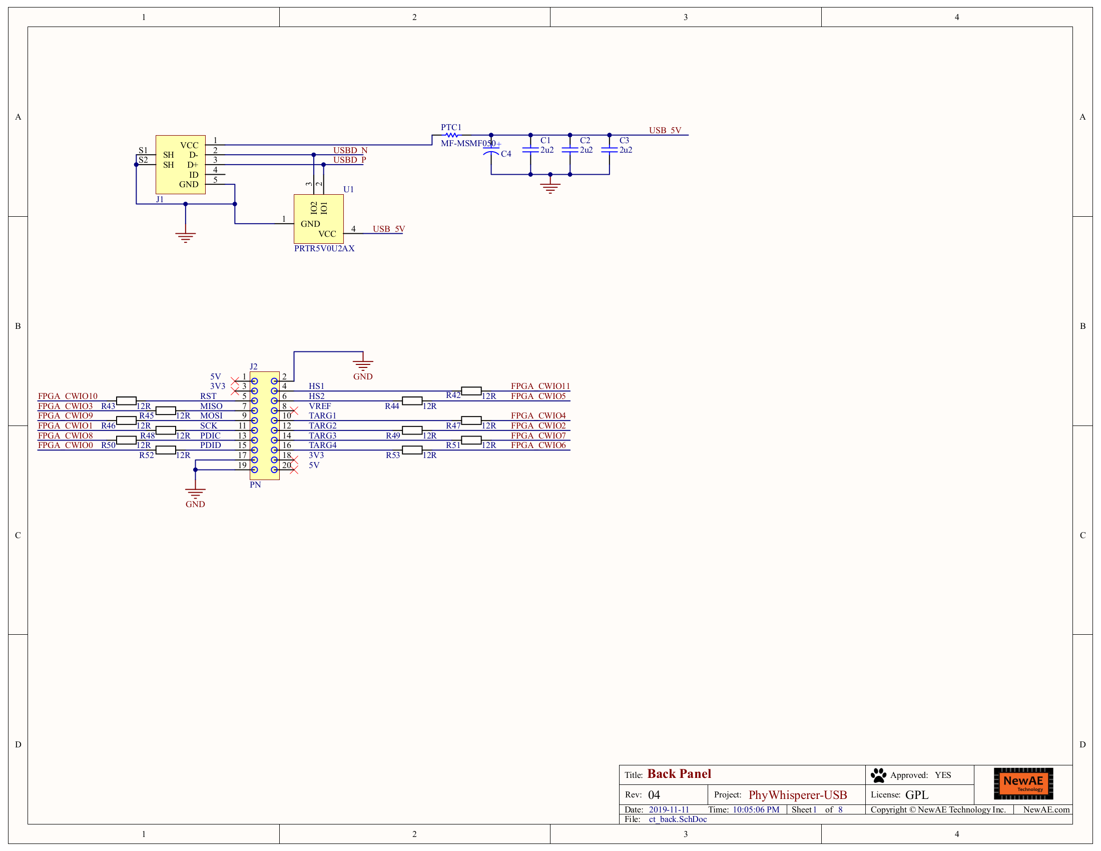
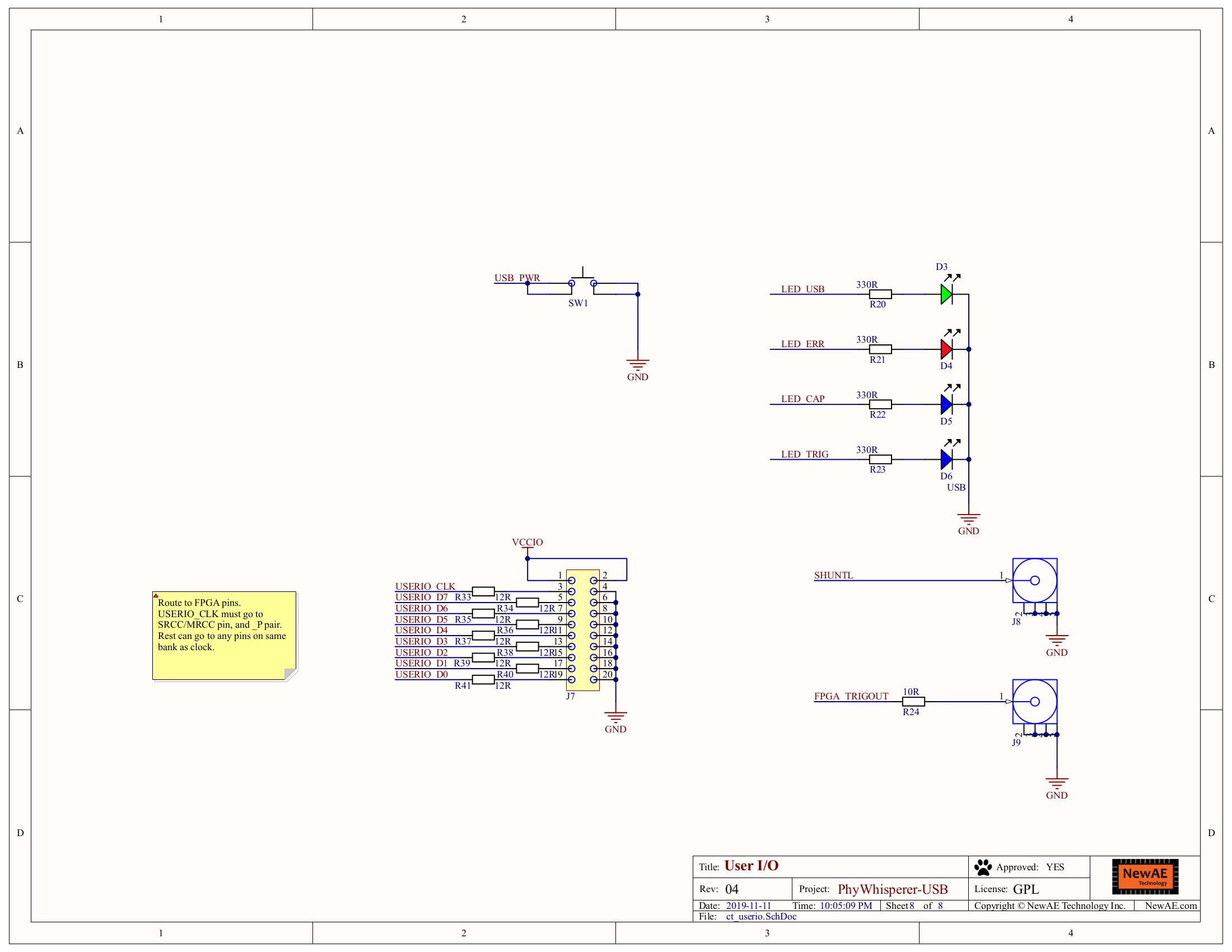
This PhyWhisperer also has a ChipWhisperer 20-pin connector (documented on the ChipWhisperer-Lite's doc page) for easy connection to other NewAE products, as well as a digital IO header connected to the PhyWhisperer's FPGA. Its pinout is as follows:
| Number | Name | Description |
|---|---|---|
| 1 | VCCIO | FPGA IO Voltage (3.3V) |
| 2 | VCCIO | |
| 3 | USERIO CLK | FPGA Clock |
| 4 | GND | Ground |
| 5 | USERIO D7 | FPGA Data 7 |
| 6 | GND | Ground |
| 7 | USERIO D6 | FPGA Data 6 |
| 8 | GND | Ground |
| 9 | USERIO D5 | FPGA Data 5 |
| 10 | GND | Ground |
| 11 | USERIO D4 | FPGA Data 4 |
| 12 | GND | Ground |
| 13 | USERIO D3 | FPGA Data 3 |
| 14 | GND | Ground |
| 15 | USERIO D2 | FPGA Data 2 |
| 16 | GND | Ground |
| 17 | USERIO D1 | FPGA Data 1 |
| 18 | GND | Ground |
| 19 | USERIO D0 | FPGA Data 0 |
| 20 | GND | Ground |
In addition, there are trigger out and shunt out connections next to the digital I/O header.
Debug
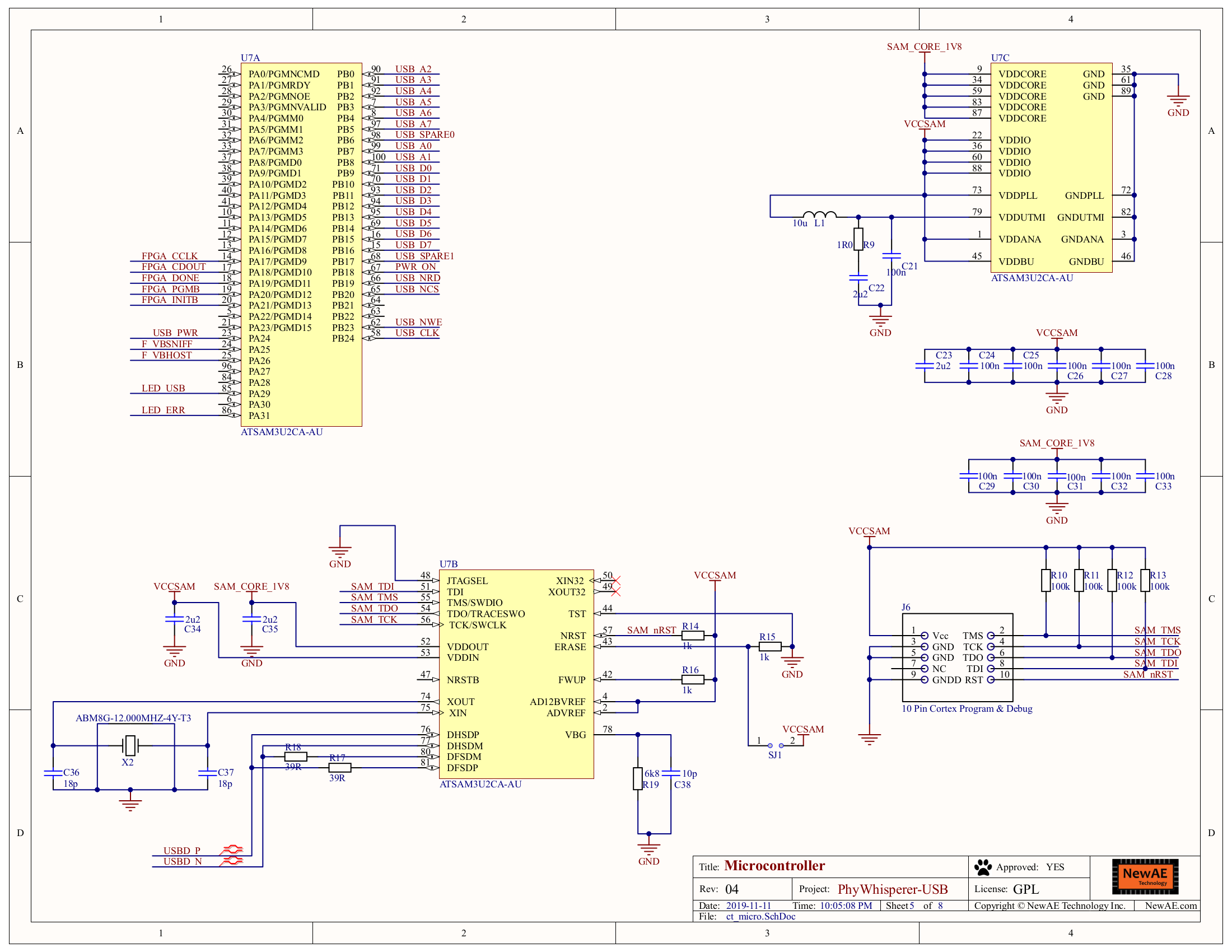
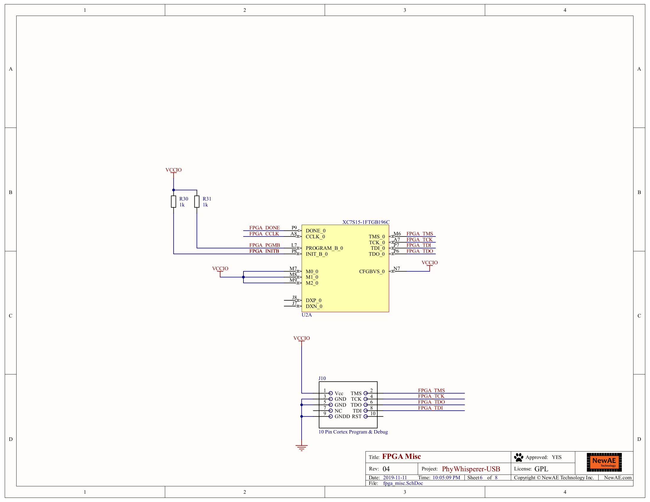
Two separate debug headers, one for the ATSAM3U microcontroller and one for the FPGA, are accessible with the case open. They are located on J6 and J10, respectively, in 10-pin Cortex Debug.
Jumper Pins
The PhyWhisperer has one set of jumper pins used modifying power supplied to the target. Typical configurations are:
- Pins 4 and 6 connected: Shunt resistor bypassed
- Pins 3 and 4 connected, pins 5 and 6 connected: Shunt resistor active
Capacitance to ground (2.2uF x2) is provided on pin 1. Pins 2 and 4 are connected internally. Pins 3 and 5 are connected internally.
Images
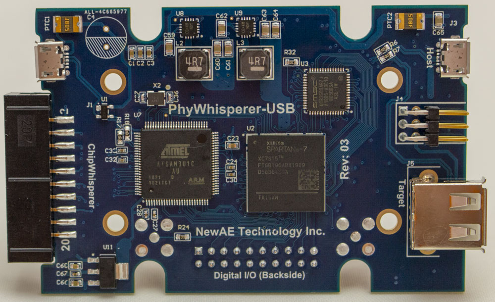
Front of PCB
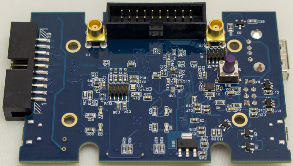
Back of PCB
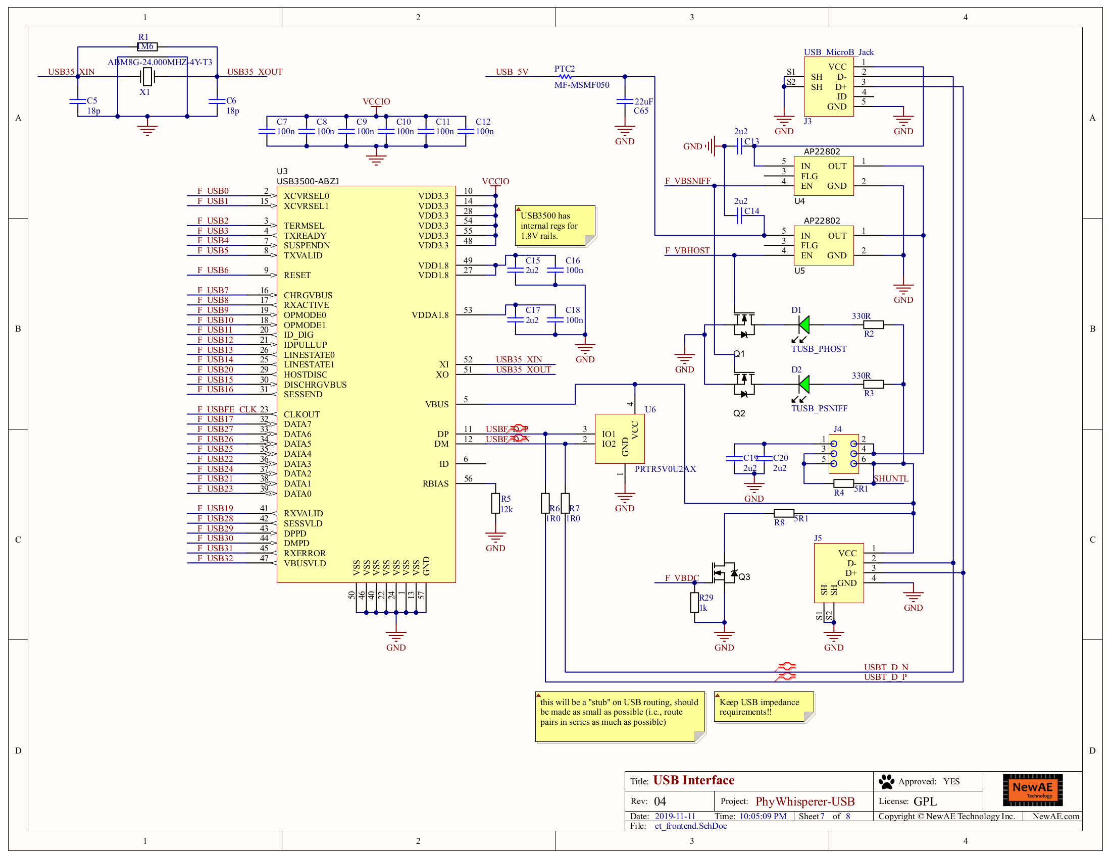
Schematic