CW303 XMEGA Target
The ChipWhisperer-Lite board has a break-away target board section. This target can be used attached to the CW-Lite or separated and connected via ribbon cable. The breakaway target board has a slightly different feature set than the CW308T-XMEGA target board.
Specifications
| Feature | Notes/Range |
|---|---|
| Target Device | ATXmega128D4-AU |
| Target Architecture | 8-bit Harvard |
| Vcc | 3.3V |
| Programming | PDI |
| Hardware Crypto | No |
| Availability | ChipWhisperer-Lite 1-part/2-part |
| Status | Released |
| Shunt | 49.9Ω |
Available with the ChipWhisperer-Lite Starter Kit
LEDs
The two LEDs on the XMEGA board are active-low, which is done to reduce the impact on power consumption in the VCC power signature. The connections are as follows:
| Item | Connection | Note |
|---|---|---|
| LED9 | PORTA.5 | Active low |
| LED10 | PORTA.6 | Active low |
Usage
Building Firmware
Building Firmware for this target requires make and avr-gcc. Installation of both these are covered in https://chipwhisperer.readthedocs.io/en/latest/prerequisites.html
If you have make and avr-gcc, you can build firmware by navigating via command line to the relevant build directory and running:
make PLATFORM=CWLITEXMEGA CRYPTO_TARGET=<CRYPTO_TARGET>
Typically CRYPTO_TARGET here is TINYAES128C, AVRCRYPTOLIB or NONE.
If you're running a Jupyter Notebook lab, typically this step will be contained within one of the code blocks.
Programming Firmware
The ChipWhisperer-Lite and ChipWhisperer-Pro have integrated PDI programmers, meaning there's no need to use an external one if you're using either. To program via the ChipWhisperer API:
# ...assuming scope is setup
# ensure device has clock and IO is setup, typically via scope.default_setup()
prog = cw.programmers.XMEGAProgrammer
cw.program_target(scope, prog, "<path/to/firmware.hex>")
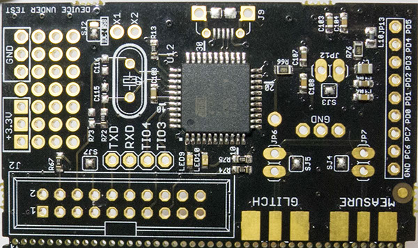
Connectors
The following shows several of the connectors available on the CW301.
20-Pin Connector
J2 is a 20-pin connector, which uses the standard NewAE 20-pin
connector pinout. See the ChipWhisperer-Lite documentation for
details.
SMA Glitch
The SMA glitch connector allows VCC glitches be inserted into the
VCC pin. This is done by shorting the resistive shunt R66. By
default it connects to the SMA measure connector, but can be
disconnected with the solder jumpers.
SMA Measure
The SMA measure connector allows power measurements to be taken
across resistive shunt R66. By default it connects to the SMA glitch
connector, but can be disconnected with the solder jumpers.
JP13
JP13 provides a pinout with several extra pins from the XMEGA
device.
Solder Jumpers
SJ2
Selects the source of the input to the VCC filter - either the
20-pin 3.3V VCC (default), or the optional voltage regulator which
derives the power from a USB-Micro connector.
SJ3
Connects the output of the VCC filter to the XMEGA VCC network.
Soldered by default.
SJ4
Connects the SMA Measure header to the resistive shunt. Soldered by
default.
SJ5
Connects the SMA Glitch header to the resistive shunt. Soldered by
default.
SJ7
Connects the VCC of the XMEGA board to VREF on 20-pin header.
Soldered by default.
Mounting Jumpers
Note the ChipWhisperer-Lite main board and target section contain a number of jumper options. By default these are not mounted, and solder jumper bridges on the PCB have been bridged to select the appropriate options when required. Some options are only solder jumpers, which to move the jumper requires a soldering iron to bridge or clear the appropriate connections.
The following lists jumpers on the ChipWhisperer-Lite / Target Section:
- JP7 connects the "MEASURE" SMA to the XMEGA VCC Rail. Shorted by default with SJ4
- JP6 connects the "GLITCH" SMA to the XMEGA VCC rail. Shorted by default with SJ5
- JP12 can be used to feed an external voltage into the XMEGA VCC rail. By default SJ3 connects this to 3.3V
- SJ2 selects if the 3.3V rail comes from the 20-pin IDC connector (i.e. ChipWhisperer-Lite board) or via an optional LDO and USB connector
Building firmware
The XMEGA uses AVR architecture and needs an AVR compiler. The target
firmware can be found under the
chipwhisperer/hardware/victims/firmware/ directory in their project
(e.g. simpleserial-aes, basic-passwdcheck) folder.
- Atmel AVR-GCC standalone - see Atmel avr-gcc standalone (registration required)
- WinAVR. Last release - 2010, see WinAVR Page (no registration required)
To build the code, follow these steps:
-
cdto the project directory with the firmware source (.c) and makefile, and runmake: cd c:\chipwhisperer\hardware\victims\firmware\make PLATFORM=CW303 CRYPTO_TARGET=AVRCRYPTOLIB where the \<> part is changed to the project name. If this is successful, you'll see an output like the following: 
If instead you get an error something like
make: *** No rule to
make target `simpleserial.elf', needed by `elf'. Stop.
, this means a required file was missing. -
The compiled firmware file you will use to program the target will have the format
<sourcefile name>-CW303.hex, where the <> part will change based on the project.
Schematic
