CW1101 ChipWhisperer-Nano
The ChipWhisperer-Nano is the lowest cost platform for performing side-channel power analysis attacks in training and educational environments. This device has a smaller subset of features compared to the ChipWhisperer-Lite or -Pro, but still allows you to perform many of NewAE's side channel tutorials and demos.
NOTE: This page will only cover the capture side of the board.

Available in the ChipWhisperer-Nano Starter Kit
Software Docs/Installation
https://chipwhisperer.readthedocs.io/
Quick-Start Guide
Like with the 1-part CW1173, hardware setup is easy! Simply use a micro-usb cable to connect the ChipWhisperer-Nano to a computer or laptop.
Once that's done, follow our software/driver installation guide at chipwhisperer.readthedocs.io, which will take the rest of the way towards learning about side channel attacks!
Product Highlights
ChipWhisperer-Nano is an ultra low-cost platform for side-channel power analysis & voltage fault injection. It has the following features:
- ADC capable of sampling up to 20 MS/s, using either external clock (synchronous to device) or internal clock (both synchronous and asynchronous).
- ADC hardware trigger uses rising-edge input and starts sampling on first device clock after trigger line going high, samples for user-configurable length.
- STM32F030 target for loading example code onto, including a programmer built into the ChipWhisperer-Nano.
- Crowbar based VCC glitching, approx 10nS resolution on glitch width and offset (glitch offset from trigger with up to 200nS jitter).
It is primarily designed for power analysis demonstrations and training programs. It is also available as a module without a target for integration onto a target board, as one option for ChipWhisperer-Enabling your development platforms.
Specifications
| Feature | Notes/Range |
|---|---|
| ADC Specs | 8-bit 20MS/s |
| ADC Clock Source | Internally generated, external input |
| Analog Input | AC-Coupled, fixed gain of ~10dB |
| Sample Buffer Size | 50 000 samples |
| ADC Decimation | No |
| ADC Offset Adjustment | No |
| ADC Trigger | Rising-edge |
| Presampling | No |
| Phase Adjustment | No |
| Capture Streaming | No |
| Clock Generation Range | 60MHz, divisible by 1, 2, 4, 8, or 16 |
| Clock Output | Regular only |
Triggering
| Feature | Notes/Range |
|---|---|
| Modules | Basic |
| Analog Trigger | N/A |
| Basic Trigger Inputs | TIO 4 |
| Basic Trigger Combination | N/A |
IO
| Feature | Notes/Range |
|---|---|
| GPIO Voltage | 3.3V |
| Logic Outputs | TIO 1-4, nRST, PDIC, PDID |
| Logic Inputs | N/A |
| UART Serial | TIO 1 (RX), TIO 2 (TX) |
| Clock | Fixed, HS2 output, HS1 Input |
| Trigger Out | No |
| Programmers | STM32F UART |
| Power rails | 3.3V |
Glitch
| Feature | Notes/Range |
|---|---|
| Voltage Glitching | Yes |
| Clock Glitching | No |
| Glitch Outputs | Glitch-Only |
| Glitch Width* | Time increments between [0, 2^32) increments |
| Glitch Width Increments | ~8.3ns |
| Glitch Offset | Time increments between [0 , 2^32) increments, ~200ns jitter |
| Glitch Offset Increments | ~8.3ns |
| Glitch Cycle Offset | N/A |
| Glitch Cycle Repeat | N/A |
| Voltage Glitch Type | Low-power crowbar |
| Voltage Glitch Pulse Current | 4A |
| Glitch Trigger | Rising-Edge |
* Actual glitch width will be affected by cabling used for glitch output
USB
| Feature | Notes/Range |
|---|---|
| USB | USB 2.0 Full Speed |
| VendorID | 0x2B3E |
| ProductID | 0xACE0 |
| Interfaces | Vendor + CDC (CDC available on firmware >= 0.30) |
| WCID (Windows 10 automatic driver installation) | ✅ (firmware >= 0.22) |
Using the ChipWhisperer-Nano
All communication with the ChipWhisperer-Nano is done through ChipWhisperer's Python API, which is documented on our ReadTheDocs Page.
ChipWhisperer also has many Jupyter Notebook tutorials/labs, which serve as learning material for side-channel
attacks, as well as examples on how to use the ChipWhisperer API. If you followed the install
instructions on ReadTheDocs, this will be in the jupyter/ folder in the place you installed
ChipWhisperer.
We also have full courses available at https://learn.chipwhisperer.io/ that supplement the Jupyter Notebook tutorials.
Using from Other Languages
While the ChipWhisperer API is written in Python, any language that can talk to libusb should be compatible. This will require you to write your own backend and is officially unsupported by NewAE.
Connectors
Using Glitch Port
The glitch port can be activated by increasing scope.glitch.repeat:
scope.glitch.repeat = 10 # ~83ns glitch

scope.glitch.repeat = 0 # no glitch
Using Measure Port
The "MEASURE" port is the input to the low-noise amplifier and ADC.
20-Pin Connector
The 20-pin connector carries power and IO pins between the ChipWhisperer-Nano and the target board. The pinout is as follows:
| Number | Name | Dir | Description |
|---|---|---|---|
| 1 | +VUSB (5V) | O | Not Connected on ChipWhisperer-Nano. |
| 2 | GND | O | System GND. |
| 3 | +3.3V | O | +3.3V to Target Device, 200mA available. |
| 4 | FPGA-HS1 | I/O | High Speed Input Clock In |
| 5 | PROG-RESET | I/O | Target RESET Pin (nRST) |
| 6 | FPGA-HS2 | I/O | High Speed Output Clock Out |
| 7 | PROG-MISO | I/O | Unused |
| 8 | VTarget | I | Drive this pin with desired I/O voltage in range 1.5V-5V. |
| 9 | PROG-MOSI | I/O | Unused |
| 10 | FPGA-TARG1 | I/O | TargetIO Pin 1 - UART RX or user output IO |
| 11 | PROG-SCK | I/O | Unused |
| 12 | FPGA-TARG2 | I/O | TargetIO Pin 2 - UART TX or user output IO. |
| 13 | PROG-PDIC | I/O | Used for putting STM32 into bootloader mode |
| 14 | FPGA-TARG3 | I/O | TargetIO Pin 3 - User output IO. |
| 15 | PROG-PDID | I/O | User output IO |
| 16 | FPGA-TARG4 | I/O | TargetIO Pin 4 - Trigger Input. |
| 17 | GND | O | |
| 18 | +3.3V | O | |
| 19 | GND | O | |
| 20 | +VUSB (5V) | O | Not Connected on ChipWhisperer-Nano. |
Examples of Tutorials you can Run
The ChipWhisperer-Nano is capable of completing many of NewAE's tutorials and labs. For example, it can complete the following:
- SCA101 (except for the UART triggering lab)
- SPA attack on a password check
- DPA and CPA attacks on AES
- CPA attack on MBED-TLS AES implementation
- Fault101 (voltage glitching only)
- Corrupting calculations
- Password bypass
- DPA attack on XOR password check
If you were to attach an external target, you could also do the following:
- Perform a CPA attack on a hardware AES accelerator.
- Perform a power analysis attack on a FPGA target.
- Perform the LPC1114 tutorial.
- Connect to CW308 UFO Board for use with a wide variety of targets.
Limitations compared to ChipWhisperer-Lite and Pro
The ChipWhisperer-Lite and Pro both use an FPGA for performing all clock routing, in addition to using better ADCs and analog front ends. Fundamentally, the design of the ChipWhisperer-Nano means it has the following major limitations:
- Sampling clock in external mode directly follows the input clock (no ability to multiply/divide/offset clock as in CW1173/CW1200).
- Sampling clock in internal mode limited to specific fixed divisions of 240 MHz PLL clock.
- Fixed analog front-end gain of approx 10dB.
- ADC limited to 20MS/s (can be overclocked slightly, up to 30MS/s but not guaranteed).
- No ADC offset to delay capture for some specific number of cycles after the trigger.
- Cannot generate clock glitching waveforms.
- VCC crowbar limited to coarse offset and width steps.
- Considerable jitter on glitch offset (due to interrupt-based source).
- Rising edge trigger only.
- Full-speed USB instead of high-speed USB.
Note that despite these limitations, ChipWhisperer-Nano can be used for attacking real devices. You can attack hardware crypto running on a microcontroller, or use power-analysis to recover a bootloader password or key. The fundamental synchronous architecture of the device (which powers all of our capture hardware tools) means it achieves considerably better performance than a regular asynchronous oscilloscope, even when that oscilloscope is running 5-20x faster.
Connecting to External Targets
You have two options for connecting to external targets: to either break off the STM32F0 end, or to program it with a loop that keeps all I/O in tristate mode. Either way you will also need to add the following connectors:
- 20-pin connector (follows standard 20-pin pinout).
- Either 3-pin headers on MEASURE and GLITCH, or SMA connectors (only if end is broken off).
Tri-State via Program
If using the tri-state mode, you should ensure the PDIC line is held LOW to avoid accidentally entering bootloader mode on the STM32F0.
There will be some additional noise due to the STM32F0 being on the power line. You can reduce this by opening the solder jumper that links the STM32F0 to the input stage.
Cutting end Off
Similar to the ChipWhisperer-Lite, you can break off the end section. To do that, you will have to do the following:
- Use an xacto knife or similar to deeply score along the perforated holes on both top and bottom, being very careful not to cut towards or near your hand. You will need to hold the CWNANO in an appropriate jig or vice.
- Align the holes on the edge of a hard surface (suggested: block of wood), and firmly push down on the target end while pushing against down the PCB against the edge. The objective is to avoid flexing the PCB which is likely to break components or solder joints.
- With appropriate protection from the fiberglass dust, lightly sand the broken edges.
Beta Versions
There exist TWO beta (pre-release) versions floating around. The two versions were released at these events:
- CHES 2018 version
- arm TechCon version
These versions have some limitations. First, they have not been well tested and were not built under the normal production processes, so are not guaranteed to be as reliable w.r.t. soldering. Second, they have some specific hardware changes relative to the production units:
- arm TechCon and CHES version (-01 and -02 PCB revs): If you cut/snap the target off, the GPIO4 (trigger) pin is not connected. As this pin is required to be used for the ADC trigger, we recommend not cutting the targets off these versions. The GPIO4 trace is incorrectly routed THROUGH the target section. If you'd like to use an external target, either erase the STM32F0 or remove the IC.
- CHES version (-01 PCB rev) does not have the amplifier on the front-end. This results in poor analog performance.
Upgrading SAM3U Firmware
Checking Firmware Version
The firmware version can be accessed as follows:
>>> import chipwhisperer as cw
>>> scope = cw.scope()
>>> print(scope.fw_version)
{'major': 0, 'minor': 11, 'debug': 0}
The version of the newest firmware can be printed as follows:
>>> import chipwhisperer as cw
>>> scope = cw.scope()
>>> print(scope.latest_fw)
{'major': 0, 'minor': 11}
If a firmware update is available, the user will be warned when connecting to the scope:
>>> scope = cw.scope()
WARNING:root:Your firmware is outdated - latest is 0.12. Suggested to update firmware, as you may experience errors
See https://chipwhisperer.readthedocs.io/en/latest/firmware.html
Upgrading Firmware
See https://chipwhisperer.readthedocs.io/en/latest/firmware.html for instructions on how to update the SAM3U firmware.
Erase Pins
If you are unable to connect to the ChipWhisperer-Nano to erase its firmware, the SAM4S firmware
can also be erased by shorting SJ1 the Nano is on. With the USB connector
above, SJ1 is on the backside of the board, near the top, and has the text ERASE below
it.
After shorting the pins, you should see no LEDs lit (the ERROR LED may be very dimly lit).
Linux usbserial module Workaround
There is an issue in some versions of Linux, where the SAM3U is not assigned a serial port when it enters bootloader mode. Here are some steps to resolve this issue (Note. this is not a permanent fix, you must go through these steps each time you put your ChipWhisperer into bootloader mode.). These steps assume you've already put ChipWhisperer into bootloader mode.
- Unplug your ChipWhisperer (Leave unplugged until instructed otherwise)
- Reboot your computer
- Once logged in again, open a terminal session
- Run this command:
sudo modprobe usbserial vendor=0x3eb product=0x6124 - Plug your ChipWhisperer back in
- Check that a serial port is now open using:
ls -l /dev/ttyUSB*

You should now be able to program the bootloader from ChipWhisperer Capture through the port you created
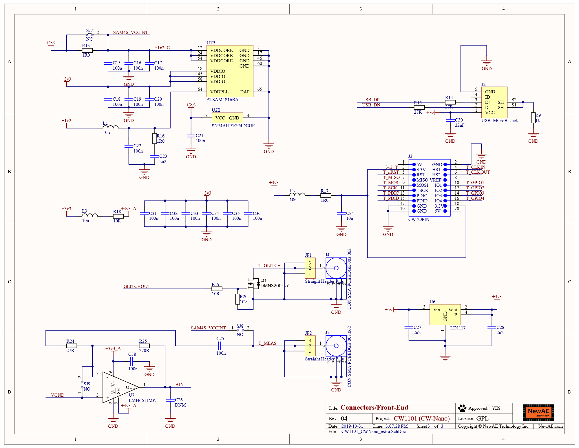
Schematic

Errata
ADC/Target Phase Offset Causes Clipping
The Nano uses a clock divider in the SAM4S to generate the target and ADC clocks. The SAM4S doesn't provide a method of synchronizing these clocks, meaning the phase offset between the two will be different each time the chip is started. For some offsets, this can cause recorded power traces to clip.
Note that depending on where the clipping is happening, power traces that clip may still work for power analysis.
Workaround
Use scope.reset_clock_phase() to restart the PLLs until power traces do not clip.