Tips and Tricks
Some additional tips and tricks that can help you apply side channel attacks in real world scenarios!
Downsampling
The ChipWhisperer's downsampling factor allows the ADC to discard a number of samples. For example, with a downsampling factor of 4, only every 4th sample is kept - the other 3 are thrown out before the trace is sent back to the computer. This feature has several uses:
- On the ChipWhisperer Lite, space is very limited - the maximum sample count of 24400 can make it difficult to find interesting features in traces or capture longer operations like ECC. Using downsampling can make it easier to find interesting features in these traces.
- On the ChipWhisperer Pro, the sampling rate in streaming mode is limited by the USB connection's data rate: the maximum sampling rate is approximately 10 MS/s. Using downsampling can make it easier to fit under this limit.
For all of these use cases, make sure you're already running the ADC clock slowly if possible. Don't use a 4x faster ADC just to throw out 3/4 of the samples!
Caution: be careful using the ChipWhisperer Pro's SAD trigger! The discarded ADC samples are still used as input for the SAD trigger module. If your reference trace was captured using downsampling, then the ChipWhisperer will never find this downsampled pattern in the raw samples.
Example
The following shows the standard AES, captured on the CW-Lite at 1:128 downsampling (with a 29.538 MS/s ADC, giving effective sample rate of 230.77 KS/s):
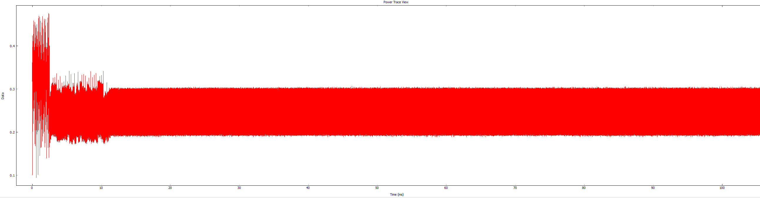
This capture remains synchronous to the target device still, despite the huge downsampling factor. This allows attacks to succeed at surprisingly low sample rates (this sample rate is probably a little extreme, but you can see the 100 mS capture time).
OpenADC Low Frequency Input
This is based on the following technical report: A Four Channel Beam Current Monitor Data Acquisition System Using Embedded Processors
You can greatly increase the low-frequency response by adjusting two items:
- Change capacitor C33
- Remove solder jumper SJ1
See the linked report above for details.
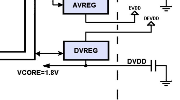
Targets with Internal Regulators
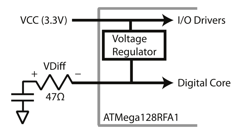
Many devices will have an internal voltage regulator - for example the following excerpt from the ATMega128RFA1 datasheet shows a 3.3V input being regulated by an internal voltage regulator:
This may seem to be a problem for performing side-channel power analysis. Some devices have a way to shut down the internal regulator (either via programming, or via an external pin).
Using Internal Voltage Regulator
There is two possible ways around this: inserting a shunt into the capacitor, or "overpowering" the internal regulator such that it shuts down. The first way means simply using a shunt resistor as shown below, where we measure from the negative side of the "VDIFF" shown here:
Note on certain devices there may be a large low-frequency noise from the internal regulator. You can improve the results in those cases by:
- Using a high-pass external filter.
- Using a differential probe.
- Using the external voltage regulator connection (shown below).
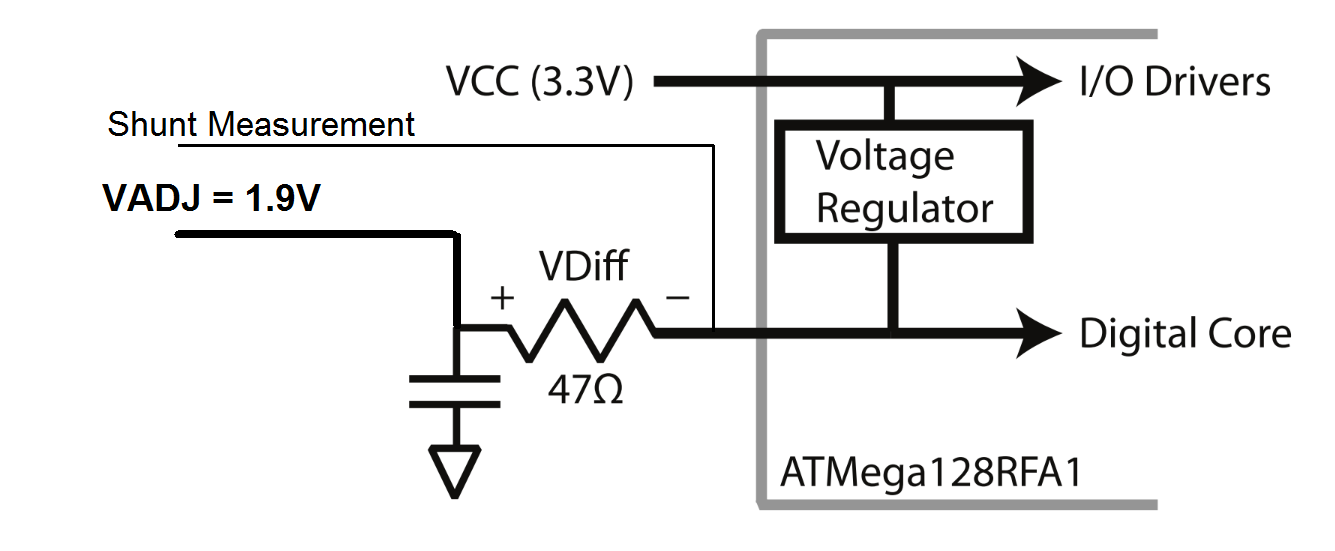
Using External Voltage Regulator
Alternatively, we can send in a "slightly" higher internal voltage. The internal voltage regulator should see the feedback voltage is above the target voltage, and thus will not pass any voltage. The result is a lower-noise signal. This looks as follows:
You may need some experimentation to determine the ideal voltage input. You don't want it too high or the magic smoke may be released, but if it's too low the internal voltage regulator will kick in causing additional noise.
On the CW308 UFO board this is easily done by moving J14 to the right side (connecting VADJ to the filter input), and adjusting VADJ as appropriate. Before doing this though you should preset VADJ to an appropriate value (i.e., ensure using a DMM the voltage is set to around 1.2V if using a 1.2V core).
Due to the potential for significant damage, it's suggested to always set VADJ back to the lowest level once done with a target.
Improving Glitch Precision
If you're using a target with its own clock source, it's possible to set up the glitch module to have a higher resolution. The steps to do this are:
- Set the CLKGEN input source to
EXTCLK. - Set up the multiply and divide values to make CLKGEN faster than the external clock (for example, Multiply = 10 and Divide = 1). Keep in mind that extremely high clock speeds won't work.
- Set the glitch module's clock source to CLKGEN.
Now, one period of the glitch module's output will be a fraction of the target's clock period.
This overclocked glitch module is best used with the Enable Only output mode, which generates a single pulse that can last for many clock cycles. The Ext Trigger Offset and Repeat values are in terms of the glitch module's clock, so the pulse's start and end times can be tuned by fractions of a target period.
If the target is using an internal clock source, you can use the ChipWhisperer's internal CLKGEN in a similar way. Though the glitch won't be synchronous with the target's clock, you can still insert extremely precise glitches with this method.