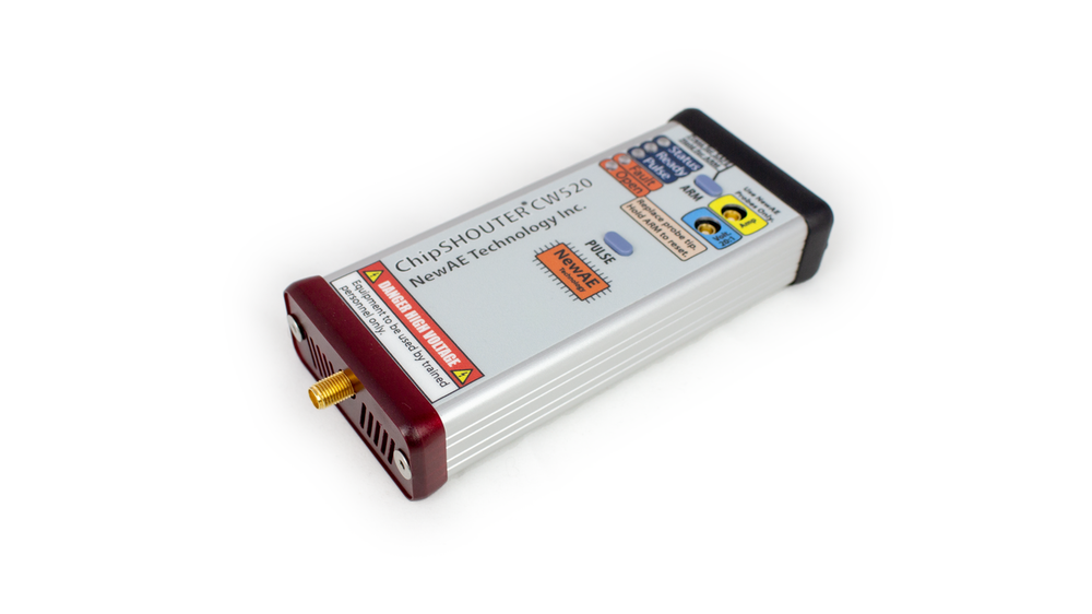
CW520 ChipSHOUTER
The CW520 (ChipSHOUTER) is a fully-featured Electromagnetic Fault Injection platform that can be used to discover and characterize vulnerabilities in embedded systems. ChipSHOUTER makes EMFI available to test labs, engineering development firms, educators, and embedded enthusiasts. With a flexible API and bundled practice targets the system is a platform for experimentation and education right out of the box. Paired with an X-Y table and some basic python scripting the ChipSHOUTER becomes a fully automatable EMFI platform capable of precision testing and fault characterization.
Software Docs/Installation
https://chipshouter.readthedocs.io/en/latest/
SAFETY INFORMATION
The ChipSHOUTER generates large voltages and electromagnetic fields that can be hazardous to human health and can cause nearby devices to malfunction. Carefully read the safety sections in the ChipSHOUTER manual, available on the ChipSHOUTER github before use.
Product Highlights
- High side coil drive means the tip isn't connected directly to the high voltage capacitor bank, reducing shock risk
- Sophisticated fault detection system helps ensure user safety and prevents damage to the device
- Basic and pulse output patterns
- Low latency hardware trigger allows easy interface with other devices with triggering mechanisms, such as oscilloscopes or the ChipWhisperer platform
- Serial interface with Python API allows easy automation of glitch insertion
- Variety of fault injection tips available
Specifications
I/O Characteristics
| Characteristic | Specification |
|---|---|
| Serial command interface | 3.3V CMOS Serial, 115200, 8N1 |
| Protocol | ASCII command prompt, Binary |
| Serial connection | RJ12 connector with GND, TX/RX, 3.3V output and switchable pulse/arm pin. |
| Hardware trigger connector type | SMB connector, center positive |
| Hardware trigger threshold | 2V |
| Hardware trigger absolute maximum ratings | -0.5V to 6.5V |
| Hardware trigger impedance | 50/1.8kΩ (switchable) |
| Hardware trigger level | Active-high / Active-low (Switchable) |
| Injected waveform monitor | BNC connector for mating with standard 1MΩ || 10-25pF oscilloscope input. Adjustable compensation trimmer for fine tuning match. |
| Voltage monitor attenuation | 20x attenuation |
| Voltage monitor output range | ±-25V into properly matched oscilloscope input |
High Voltage Characteristics
| Characteristic | Min | Typ | Max | Units |
|---|---|---|---|---|
| Programmable voltage range | 150 | 500 | V | |
| Charge rate | 30 | 40 | V/ms | |
| Charge energy | 625 | mJ | ||
| Measured voltage accuracy via digital interface | ±(5%+10V) |
Pulse Source Characteristics
| Characteristic | Min | Typ | Max | Units |
|---|---|---|---|---|
| Basic pulse generator | ||||
| Pulse width range | 80 | 960 | ns | |
| Pulse width resolution | 80 | ns | ||
| Pulse width jitter | 350 | ns | ||
| Pulse dead-time (between repeats) | 1 | 1000 | ms | |
| Pulse repetition count (per trigger event) | 1 | 10000 | ||
| Programmable pattern generator | ||||
| Pulse width resolution (time-steps) | 20.83 | ns | ||
| Time-steps per pulse | 1 | 5000 | Time-steps | |
| Total pulse width | 0.0208 | 100 | us | |
| Pulse output state per time-steps | 1/0 | |||
| Pulse width jitter - tested pulse width of 80ns | 350 | ps std-dev | ||
| Hardware Input Trigger | ||||
| Delay - tested high voltage of 150V to 500V | 75 | ns | ||
| Delay jitter - tested high voltage of 150V to 500V | 150 | ps std-dev | ||
| Width jitter - tested high voltage of 150V to 500V | 800 | ps std-dev | ||
| Width jitter - tested high voltage of 300V to 500V | 220 | ps std-dev |
Inserted Pulse Characteristics
| Characteristic | Min | Typ | Max | Units |
|---|---|---|---|---|
| Pulse width into 1mm injection tip | 15 | 80 | TYPICAL ns | |
| Pulse width into 4mm injection tip | 24 | 480 | TYPICAL ns | |
| Minimum consecutive pulse spacing - Tested with 4mm injection tip at voltage setting of 500V | ||||
| 2 pulses | 100 | ns | ||
| 3 pulses | 175 | ns |
Examples & Documentation
- ChipSHOUTER User Manual
- NewAE Product Page
- App-Note on EMFI for Automotive Safety & Security
- Python API Documentation
- ChipSHOUTER Complete Schematic