ChipWhisperer-Husky
ChipWhisperer-Husky is the successor to the CW1173 ChipWhisperer-Lite. It has many improvements over its predecessor, including a higher resolution and faster ADC, a bigger FPGA enabling additional features that were exclusive to the ChipWhisperer-Pro, and more flexible clocking.
Husky-Plus has the same capabilities but with several upgraded specs, which are listed here.
Crowd Supply Page
https://www.crowdsupply.com/newae/chipwhisperer-husky
Software Docs/Installation
https://chipwhisperer.readthedocs.io/
Quick-Start Guide
Hardware setup is fast and easy! Connect your ChipWhisperer-Husky to a computer using a USB-C cable. Next, connect both a 20-pin cable between the CW 20-pin Connector and the target, as well as a coax cable between the measure POS SMA (if you're doing power analysis) or the glitch SMA connector (if you're doing voltage glitching) and the SMA connector on the target. For other targets, check the relevant target documentation.
Once that's done, follow our software/driver installation guide at chipwhisperer.readthedocs.io, which will take the rest of the way towards learning about side channel attacks!
Product Highlights
- Synchronous (capture board and target board both use the same clock) capture and glitch architecture, offering vastly improved performance over a typical asynchronous oscilloscope setup
- 12-bit 200MS/s ADC for capturing power traces
- Can be clocked at both the same clock speed as the target, as well as integer multiples of this frequency.
- +55dB adjustable low noise gain, allowing the Lite to easily measure small signals
- Clock and voltage fault generation via FPGA-based pulse generation
- XMEGA (PDI), AVR (ISP), SAMBA (Microchip SAM) and STM32F (UART Serial) bootloader built in
- JTAG/SWD debugging lines on CW 20-pin connector, as well as JTAG compatible 20-pin digital header
- Only works via OpenOCD
- Streaming mode (>20MS/s 8-bit max) for long captures
- Trigger Out/Glitch Out SMB Connector
- Aux In/Out SMB Connector
- TraceWhisperer Arm Trace sniffing/triggering
- 20-pin User IO header (8 Data Pins), can be used for :
- JTAG/SWD (20-pin JTAG compatible)
- Arm Trace
- User Controlled
- Logic Analyzer
- Trigger pins
- Many trigger modes:
- Basic (Rising edge, falling edge, high, low)
- Analog threshold
- Analog Pattern (Sum of Absolute Difference, up to 512 samples)
- UART byte
- Edge count
- Arm Trace
- Sequenced triggers
- Glitch based on internal VCO means glitch resolution isn't based on target clock
- Multiple programmable glitches
Specifications
Analog Capture and Clock
| Feature | Notes/Range |
|---|---|
| ADC Specs | 12-bit 200MS/s (Husky Plus: 250MS/s) |
| ADC Clock Source | PLL generated/External (Integer multiple) |
| Analog Input | AC-Coupled, adjustable low-noise gain from -6.5dB to 55dB |
| Sample Buffer Size | 131124 samples (Husky Plus: 327828 samples) |
| ADC Decimation | Yes |
| ADC Offset Adjustment | Yes, [0, 2^32) clock cycles |
| ADC Trigger | Rising-edge, Falling-edge, High, Low |
| Presampling | Yes |
| Phase Adjustment | Yes |
| Capture Streaming | Yes |
| Clock Generation Range | 5-200MHz |
| Clock Output | Regular, with glitch inserted, glitch only |
Triggering
| Feature | Notes/Range |
|---|---|
| Modules | Basic, Analog, UART, Edge Count, Arm Trace |
| Analog Trigger | Sum of Absolute Difference (up to 512 samples), Analog Threshold |
| Basic Trigger Inputs | TIO 1-4, nRST, SMB, User IO D0-7 |
| Basic Trigger Combination | One of OR, AND, NAND |
IO
| Feature | Notes/Range |
|---|---|
| GPIO Voltage | 3.3V |
| Logic Outputs | TIO 1-4, nRST, PDIC, PDID |
| Logic Inputs | TIO 1-4 |
| UART Serial | TIO 1-4 assignment |
| Clock | Fixed, HS2 output, HS1 Input |
| Trigger Out | Yes |
| Programmers | STM32F UART, Atmel PDI (for XMEGA), Atmel ISP (for AVR) |
| Power rails | 3.3V |
| User IO Pins | 8 Data pins: JTAG, SWD, Arm Trace, Generic |
Glitch
| Feature | Notes/Range |
|---|---|
| Voltage Glitching | Yes |
| Clock Glitching | Yes |
| Glitch Outputs | Clock-XOR, Clock-OR, Glitch-Only, Enable-Only |
| Glitch Width * | Based on Internal PLL (600-1200MHz), 100% (enable-only) |
| Glitch Width Increments | Based on Internal PLL (600-1200MHz) |
| Glitch Offset | Based on Internal PLL (600-1200MHz) |
| Glitch Offset Increments | Based on Internal Pll (600-1200MHz) |
| Glitch Cycle Offset | [0, 2^32) |
| Glitch Cycle Repeat | [0, 8192] |
| Voltage Glitch Type | High-power, low-power crowbar |
| Voltage Glitch Pulse Current | 20A |
| Glitch Trigger | Rising-Edge |
* Actual glitch width will be affected by cabling used for glitch output
USB
| Feature | Notes/Range |
|---|---|
| USB | USB 2.0 High Speed |
| VendorID | 0x2B3E |
| ProductID | 0xACE5 |
| Interfaces | Vendor + CDC or Vendor + MPSSE |
| WCID (Windows 10 automatic driver installation) | ✅ |
| MPSSE (FTDI JTAG/SWD) | ✅ |
Using the ChipWhisperer-Husky
All communication with the ChipWhisperer-Husky is done through ChipWhisperer's Python API, which is documented on our Read the Docs Page.
ChipWhisperer also has many Jupyter Notebook tutorials/labs, which serve as learning material for side-channel
attacks, as well as examples on how to use the ChipWhisperer API. If you followed the install
instructions on Read the Docs, this will be in the jupyter/ folder in the place you installed
ChipWhisperer.
We also have full courses available at https://learn.chipwhisperer.io/ that supplement the Jupyter Notebook tutorials.
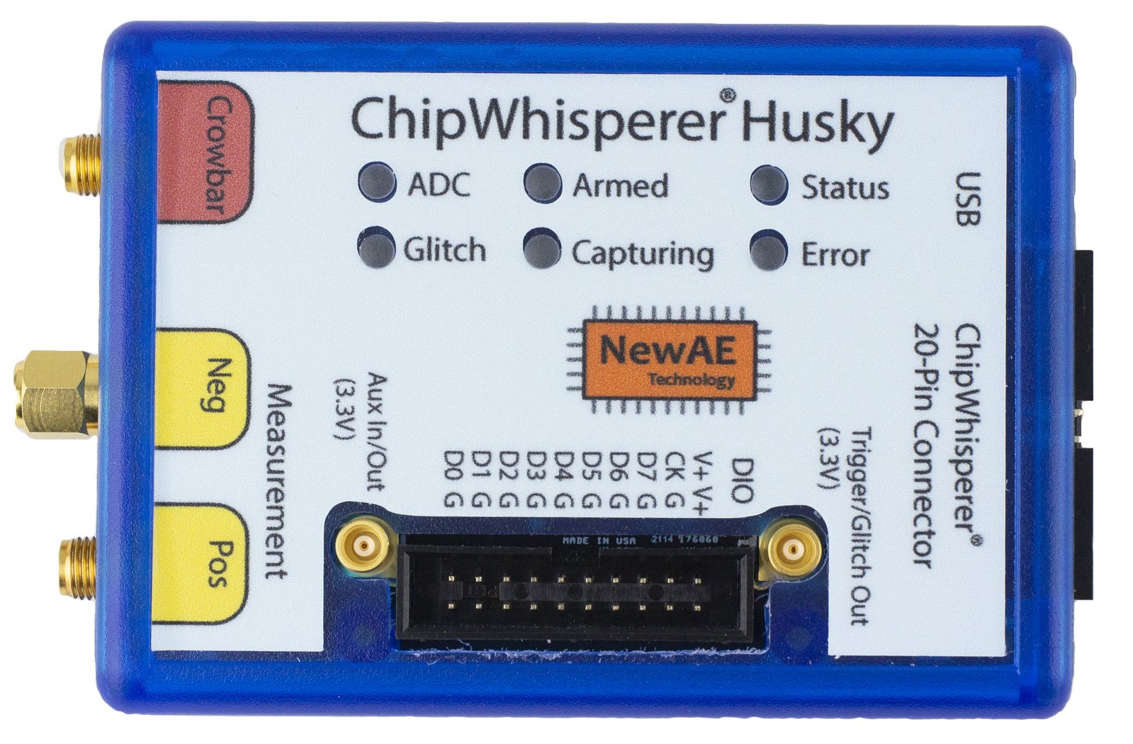
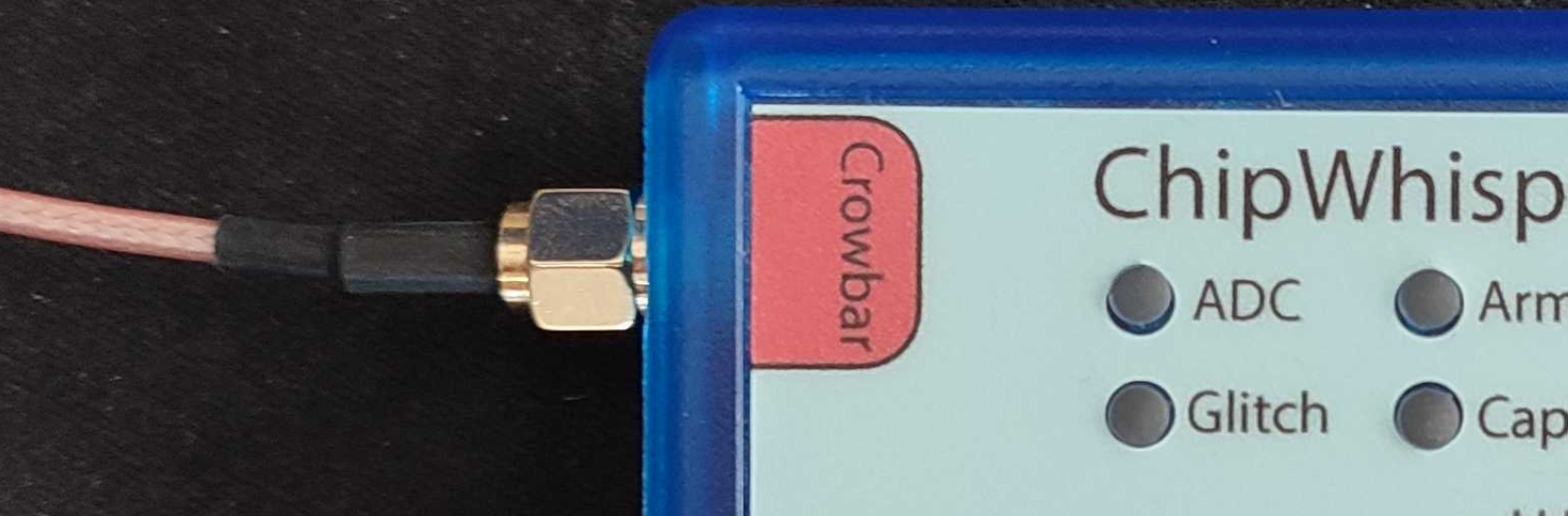
Connectors
Using Glitch Port
The "CROWBAR" port is used for voltage glitching. It's connected to two MOSFET elements, as the following figure shows:
The Husky glitch output can be commanded to turn on either of those
MOSFETs via scope.io.glitch_hp and scope.io.glitch_lp fields:
scope.io.glitch_hp = True #enable high power glitch
scope.io.glitch_hp = False #disable high power glitch

scope.io.glitch_lp = True #enable low power glitch
scope.io.glitch_lp = False #disable low power glitch
Be careful using this feature, as you don't want to short the MOSFETs for too long. It's also possible to damage the ChipWhisperer-Husky by burning these MOSFETs up if used incorrectly. See Fault101 Voltage Glitch Labs for more information.
Note that Husky's glitch module behaves differently than the Lite, Nano's or Pro's. As such, you may want to check out our notebook on Husky glitching
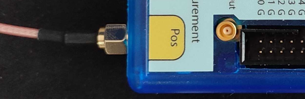
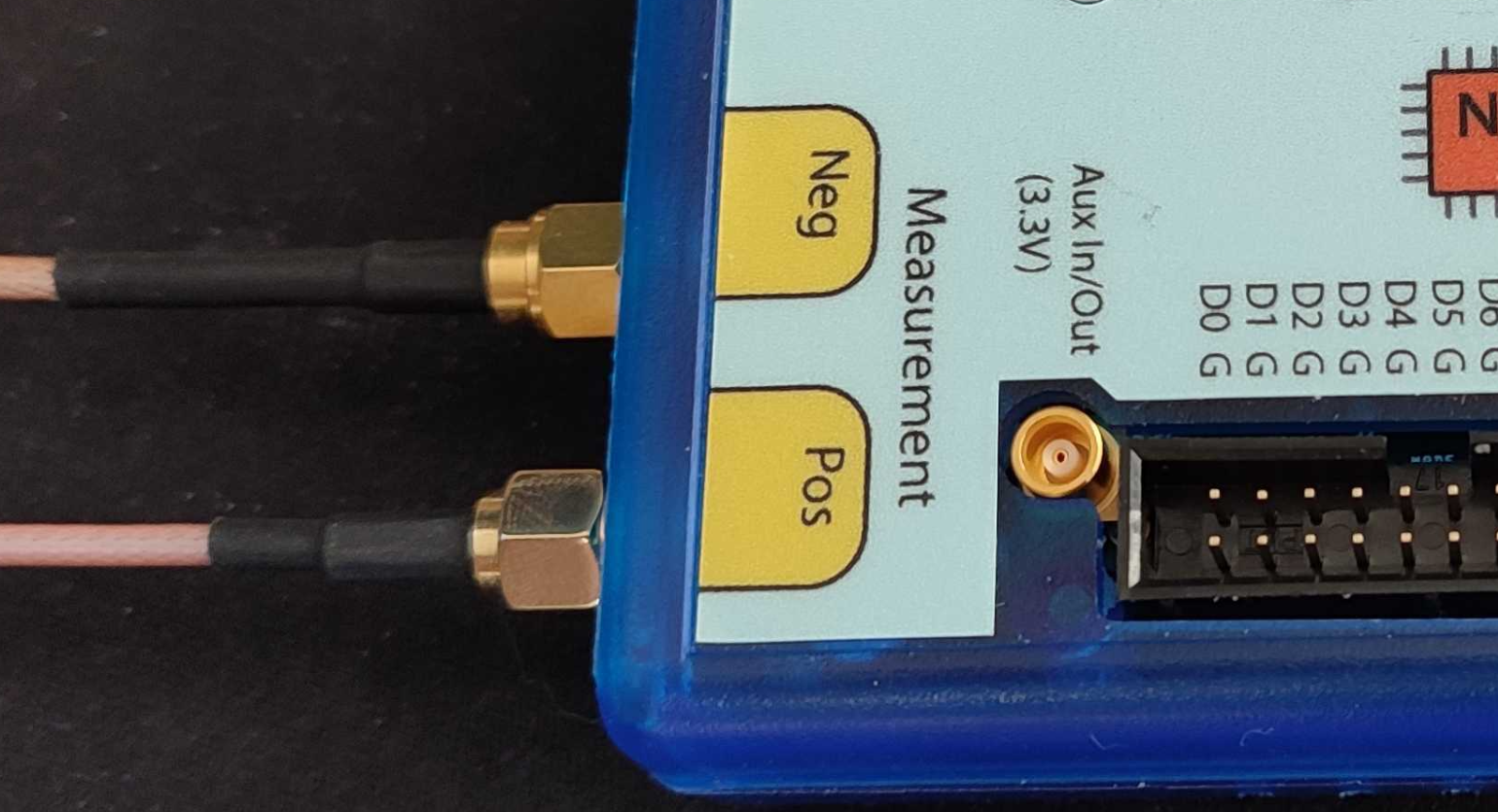
Using Measure Port
The "MEASURE" ports are the inputs to the low-noise amplifier and ADC.
The Husky includes support for both single ended and differential measurements. If you want to use the single ended measurement, it is recommended that you connect the provided short circuit cap as this makes the resulting power trace slightly less noisy and improves gain/frequency performance.
20-Pin Connector
The 20-pin connector carries power and IO pins between the ChipWhisperer-Lite and the target board. The pinout is as follows:
| Pin: Func | Pin: Func |
|---|---|
| 1: 5V (NC) | 2: GND |
| 3: 3.3V | 4: HS1 |
| 5: nRST | 6: HS2 |
| 7: MISO | 8: DNC |
| 9: MOSI | 10: TIO1 |
| 11: SCK | 12: TIO2 |
| 13: PDIC/CS | 14: TIO3 |
| 15: PDID | 16: TIO4 |
| 17: GND | 18: 3.3V |
| 19: GND | 20: 5V (NC) |
| Number | Name | Dir | Description |
|---|---|---|---|
| 1 | +VUSB (5V) | O | Not connected on Husky |
| 2 | GND | O | System GND. |
| 3 | +3.3V | O | +3.3V to Target Device, can be turned off, 200mA available. |
| 4 | FPGA-HS1 | I/O | High Speed Input (normally clock in). |
| 5 | PROG-RESET | I/O | Target RESET Pin (nRST). |
| 6 | FPGA-HS2 | I/O | High Speed Output (normally clock or glitch out). |
| 7 | PROG-MISO | I/O | SPI input: MISO (for SPI + AVR Programmer). |
| 8 | N/C | I | Not connected on Husky |
| 9 | PROG-MOSI | I/O | SPI output: MOSI (for SPI + AVR Programmer). |
| 10 | FPGA-TARG1 | I/O | TargetIO Pin 1 - Usually UART TX or RX. |
| 11 | PROG-SCK | I/O | SPI output: SCK (for SPI + AVR Programmer). |
| 12 | FPGA-TARG2 | I/O | TargetIO Pin 2 - Usually UART RX or TX. |
| 13 | PROG-PDIC | I/O | PDI Programming Clock (XMEGA Programmer), or CS pin (SPI). Also used for STM32 bootloader |
| 14 | FPGA-TARG3 | I/O | TargetIO Pin 3 - Usually bidirectional IO for smartcard. |
| 15 | PROG-PDID | I/O | PDI Programming Data (XMEGA Programmer). |
| 16 | FPGA-TARG4 | I/O | TargetIO Pin 4 - Usually trigger input. |
| 17 | GND | O | |
| 18 | +3.3V | O | |
| 19 | GND | O | |
| 20 | +VUSB (5V) | O | Not connected on Husky |
User IO Header
Like the PhyWhisperer-USB, the ChipWhisperer-Husky has a 20-pin User IO header connected to the FPGA.
The pinout is as follows:
| Pin: Func | Pin: Func |
|---|---|
| 1: 3.3V | 2: 3.3V |
| 3: Clock | 4: Gnd |
| 5: D7 | 6: Gnd |
| 7: D6 | 8: Gnd |
| 9: D5 | 10: Gnd |
| 11: D4 | 12: Gnd |
| 13: D3 | 14: Gnd |
| 15: D2 | 16: Gnd |
| 17: D1 | 18: Gnd |
| 19: D0 | 20: Gnd |
This pinout is also listed on the front panel sticker of the Husky. The following output modes are available for the data pins:
- Normal (Default) - Data pins as GPIO
- Trace - Data pins used for Arm Trace debug
- FPGA Debug - Data pins routed to internal FPGA signals
- Debug JTAG - Data pins routed for 20-pin JTAG compatibility
- Debug SWD - Data pins routed for 20-pin JTAG compatibility, SWDIO as I/O
These data pins can also be used as trigger inputs for the ChipWhisperer.
Advanced Usage
Advanced usage is covered in depth in our series of Husky-specific demo notebooks; here we provide a brief overview.
TraceWhisperer
Arm Trace is an advanced debug feature of Arm processors allowing debug information to be streamed off of a microcontroller while it is running. A more complete description is available on Arm's Website.
TraceWhisperer, an Arm Trace sniffer by NewAE, has been integrated into ChipWhisperer-Husky.
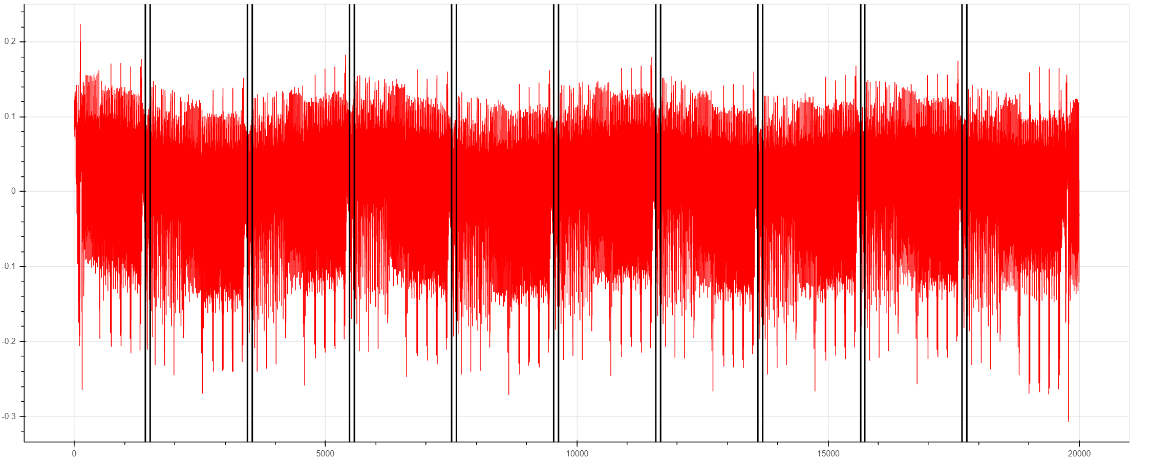
This integration enables a bunch of cool features such as identifying where in power traces instructions are being executed:
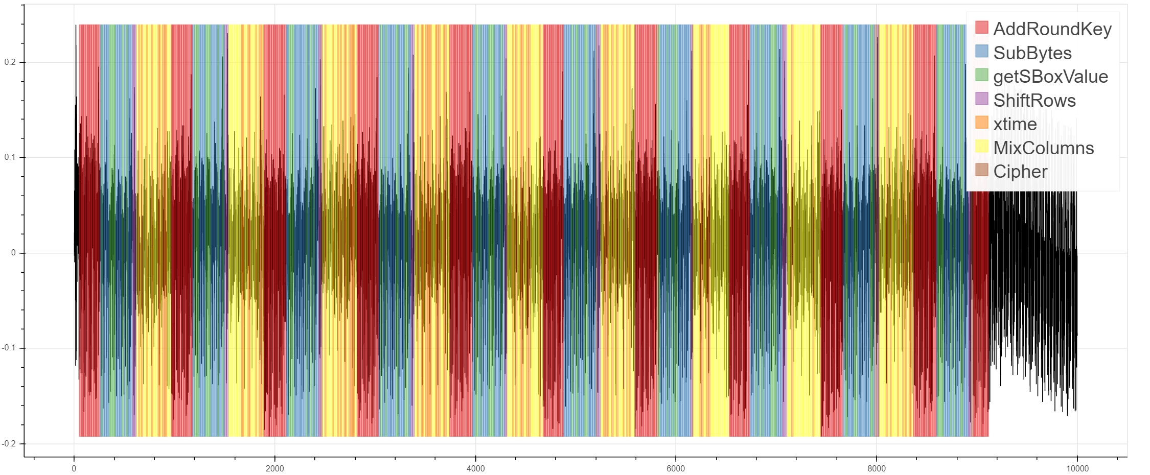
Matching power traces with the functions being executed:
And identifying time-based leakage:
You can also use ChipWhisperer-Husky to trigger based on Arm Trace data, which will be covered later.
Streaming Mode
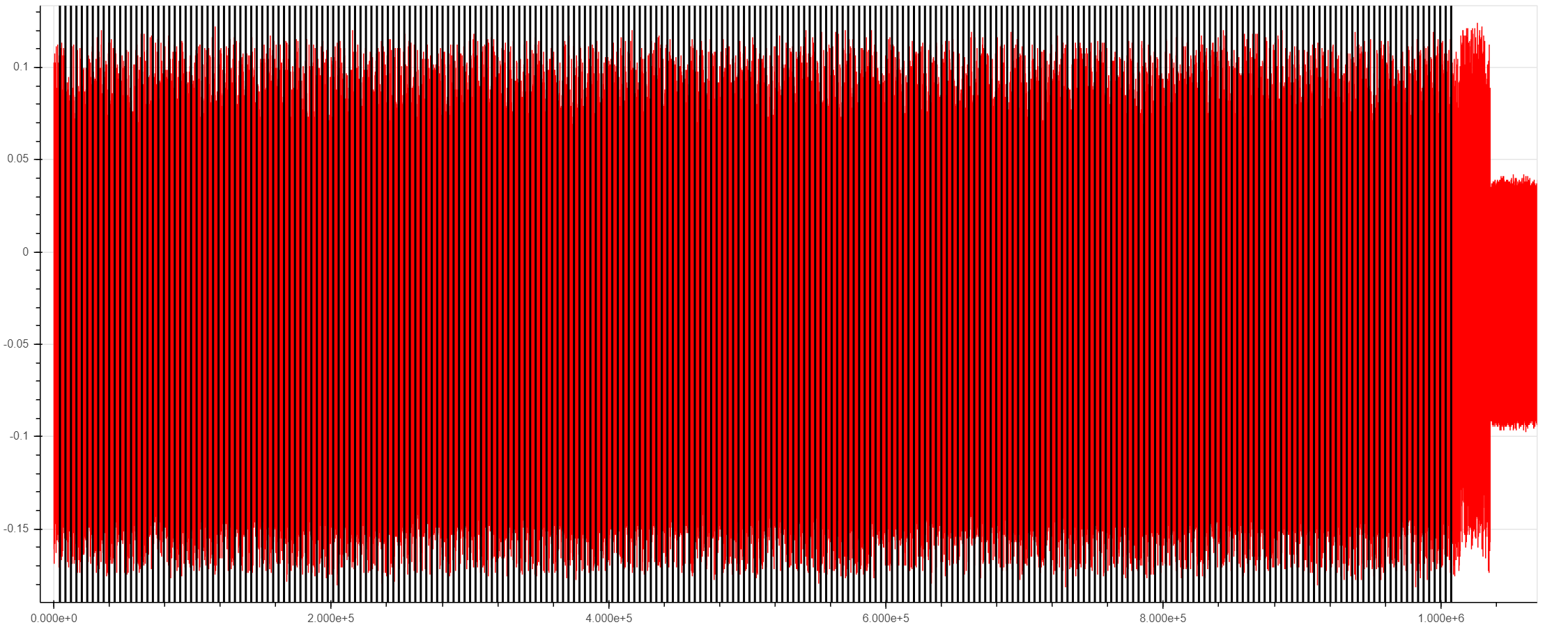
The ChipWhisperer Husky has a streaming mode that allows extremely long captures as long as relatively low sampling rates are used. For example, this plot shows an excerpt from an AES trace with 1 million samples:

If we zoom in, we can still see the familiar AES structure

This capture mode is useful for many types of attacks, including:
- Full captures of slow software AES libraries
- Power analysis on ECC/RSA
- Context switches on embedded operating systems
While streaming, the ChipWhisperer hardware sends ADC data back to the capture software while recording more samples (instead of waiting until the end of the capture). During this process, the ADC samples are sent back to the computer in packets. The packet size can be adjusted, but is 64k samples long by default. As a block diagram, this looks like:
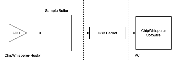
The main danger in streaming mode is that the FPGA's sample buffer can overflow if the PC doesn't request these packets quickly enough. This means that the Husky has a max sampling frequency in stream mode somewhere above 20MS/s (AKA 20MHz ADC clock) if the ADC is run in 8-bit mode. In practice the max sampling rate is usually around 25MS/s, with things like temperature, various USB factors, and the packet size affecting this value.
Trying to stream above this rate will usually cause data to be corrupted. If this happens, you will be informed of the data corruption when reading data back.
On the software end, there are two things to watch for:
-
Long captures from streaming mode (millions of points) may take several seconds to record. When working with these long captures, make sure the software's timeouts (
scope.adc.timeout) are long enough. -
Extremely long captures take a lot of memory. 64-bit Python is recommended if you plan on capturing many traces with millions of samples - you can hit the memory limit on 32-bit Python pretty quickly.
Also keep in mind that these numbers are for 8-bit captures. If you want to stream
12-bit data, the max sampling frequency will be roughly 12/8 times
slower. For example, 20MS/s at 8-bits per sample is roughly equivalent to 13MS/s at
12-bits per sample.
Multiple Programmable Glitches
Often, when glitching, you'll want to target multiple instructions at the same time. For example, glitching an RSA signature operation and capturing the malformed signature can allow you to recover the key. To guard against that, many implementations validate the signature before sending it out. As earlier ChipWhisperers could only glitch one portion of code at a time, our RSA glitch lab requires modified source code that disables this final check.
With the ChipWhisperer-Husky, this is no longer necessary. This is because of a new feature - multiple
programmable glitches, allowing it to insert up to 32 glitches with different ext_offset and repeat
based off of a single trigger. For example, you could glitch both the RSA calculation and the signature verification.
To use this new mode, begin by setting the number of glitches you want to insert:
# ... normal glitch setup
scope.glitch.num_glitches = 3 # insert 3 glitches
From here, ext_offset and repeat are replaced by arrays, allowing you to easily
set each glitch's setting. For example, we'll keep the repeat at 5 for each glitch,
but insert them at ext_offsets of 50, 200, and 500:
scope.glitch.repeat = 5 # equivalent to [5, 5, 5]
scope.glitch.ext_offset = [50, 200, 500]
Note that scope.glitch.width and scope.glitch.offset are shared between these glitches.
Trigger Module
In total, the ChipWhisperer-Husky has six different trigger methods, allowing you to perform power analysis or glitch in a large number of situations.
This page will give a quick overview of each trigger, but we also have a Jupyter Notebook that demos these triggers
Edge/Level
The edge/level detector can trigger on four different events:
- Trigger input is low (0)
- Trigger input is high (1)
- Trigger input had a rising edge (0 -> 1)
- Trigger input had a falling edge (1 -> 0)
This mode is suitable when the target is using one of the GPIO pins as a trigger signal - if you have control over the target's source code, let it output a rising edge when the encryption or other operation begins.
Analog Threshold
The Husky can also trigger on an analog threshold level. This mode is similar to the analog trigger of an oscilloscope:
scope.trigger.module = 'ADC'
scope.trigger.level = 0.3
The "level" has the same scale as the ADC data returned from the ADC. As an example,
if the device varies from -0.1 to 0.1 on the graph when idle, then spikes to
-0.3 when it does an interesting operation, a good scope.trigger.level might be
-0.2
UART
The UART trigger module looks for a pattern of characters on the trigger pin and, if it detects that pattern, outputs a trigger. Up to 8 patterns can be set at a time. Documentation for this module is available on on our Read the Docs page, but here is a quick example:
#assuming setup scope:
scope.trigger.triggers = 'tio1'
scope.trigger.module = 'UART'
scope.UARTTrigger.enabled = True
scope.UARTTrigger.baud = 38400
scope.UARTTrigger.set_pattern_match(0, 'r')
scope.UARTTrigger.trigger_source = 0
This will cause the UART trigger to match on the typical simpleserial "r..." response
from NewAE targets.
Sum of Absolute Differences (SAD)
Some targets don't have nice trigger signals to detect. Sad!
The Sum of Absolute Differences module has two 256-sample buffers. The FPGA stores the ADC's 256 most recent samples in one buffer and a fixed reference pattern in the other. Then, after every sample, it calculates whether the absolute difference between the acquired samples and the reference pattern exceeds some programmable threshold.
Moreover, Husky has a special "extended SAD" mode which allows the SAD comparison to be done over 512 samples.
This trigger allows ChipWhisperer to detect a specific pattern (for instance, an encryption operation) in a power trace without any other data.
The documentation for the SAD module can be found on our Read the Docs page.
There are many SAD settings to configure; this notebook teaches how.
Note that the SAD module does not play well with downsampling (decimation): the inputs to the SAD buffer are not downsampled. This means that downsampled traces cannot be used as a reference. If you want to use this trigger type, set up your SAD trigger with downsampling turned off first.
Arm Trace Trigger
Thanks to TraceWhisperer integration, you can trigger the ChipWhisperer-Husky based on Arm Trace data.
Due to the amount of debug information you have access to in real time with Trace, TraceWhisperer allows you to set up highly specific testing scenarios for your device under test for both power analysis and glitching.
We also have a Jupyter Notebook Demo that showcases may features of TraceWhisperer, including triggering.
Edge Count Trigger
This module counts the rising and falling edges of the trigger pin and issues a trigger after a specified number of edges. This module is very useful for triggering based on protocols that the Husky doesn't support, such as SPI, I2C, etc.
For example to trigger on the third edge of TIO1:
scope.trigger.module = 'edge_counter'
scope.trigger.triggers = 'tio1'
scope.trigger.edges = 3
Husky can also tell you how many triggers it saw. This is useful in the case that the trigger times out:
print(scope.trigger.edges_seen)
Sequenced Triggers
Husky also supports the sequencing of triggers, where a number of triggers of different types must occur in a defined sequenced in order for the scope to actually trigger. This is covered in detail in this notebook.
SMB I/O
The Husky has two additional SMB connectors that can be used for useful inputs/outputs.
The first is a Trigger/Glitch out, allowing you to use the Husky's many different trigger modules with other devices. Examples of this include using the Husky to trigger a ChipSHOUTER or an external oscilloscope.
The other SMB connector can be used as either a trigger/clock input, or as a clock output.
Upgrading SAM3U Firmware
When talking about the ChipWhisperer's firmware, there is really two parts to this:
- The FPGA Bitstream file.
- The SAM3U USB interface chip firmware.
The FPGA bitstream alone is what is normally configured by the ChipWhisperer software. This bitstream is always the most up-to-date, since it's automatically reloaded by the computer every time you power cycle the ChipWhisperer-Husky. The SAM3U firmware is not updated automatically, but it tends to change less frequently.
Checking Firmware Version
The firmware version can be accessed as follows:
>>> import chipwhisperer as cw
>>> scope = cw.scope()
>>> print(scope.fw_version)
{'major': 0, 'minor': 11, 'debug': 0}
The version of the newest firmware can be printed as follows:
>>> import chipwhisperer as cw
>>> scope = cw.scope()
>>> print(scope.latest_fw)
{'major': 0, 'minor': 11}
If a firmware update is available, the user will be warned when connecting to the scope:
>>> scope = cw.scope()
WARNING:root:Your firmware is outdated - latest is 0.12. Suggested to update firmware, as you may experience errors
See https://chipwhisperer.readthedocs.io/en/latest/firmware.html
Upgrading Firmware
See https://chipwhisperer.readthedocs.io/en/latest/firmware.html for instructions on how to update the SAM3U firmware.
Erase Pins/Button
If you are unable to connect to the ChipWhisperer-Husky to erase its firmware, the SAM3U firmware can also be erased by shorting SJ1 while the Husky is on.
Depending on what revesion of the Husky you have, you may have an erase button that you can press using a needle or wire. If present, this button will be present on the other side of the 20-pin connector from the USBC connector.
Otherwise, you must open the Husky to erase it. SJ1 is located on the same side as the 20-pin User IO header, by the 10-pin SAM3U debug header, near the middle of the board. If your Husky has the aforementioned button, SJ1 won't be present.
After shorting the pins or pressing the erase button, unplug and replug the USB connector.
Errata/Notes
C49 Capacitor
Newer ChipWhisperer Husky models (Revision D and later) include an 0402 capacitor placed at C49 which is not present in earlier models to improve performance. The recommended value of this capacitor is 47pF, which puts the cutoff frequency of this filter above the Nyquist rate of the Husky's sample rate while greatly improving performance on slower AES implementations. Note that larger capacitances may further improve low frequency performance, but will reduce the bandwidth of the Husky.
Users who wish to add, remove, or change this capacitor do so at their own risk and attempting any hardware modification will void the warranty of the device.
Schematic
Available at: https://raw.githubusercontent.com/newaetech/chipwhisperer-husky/main/schematic/NAE-CWLITE-HUSKY-03.PDF
Firmware
Firmware for the Husky can be found at https://github.com/newaetech/chipwhisperer-husky. The ChipWhisperer-Husky SAM3U firmware is in the ChipWhisperer-Husky,
while the FPGA firmware is in the chipwhisperer-husky-fpga submodule.