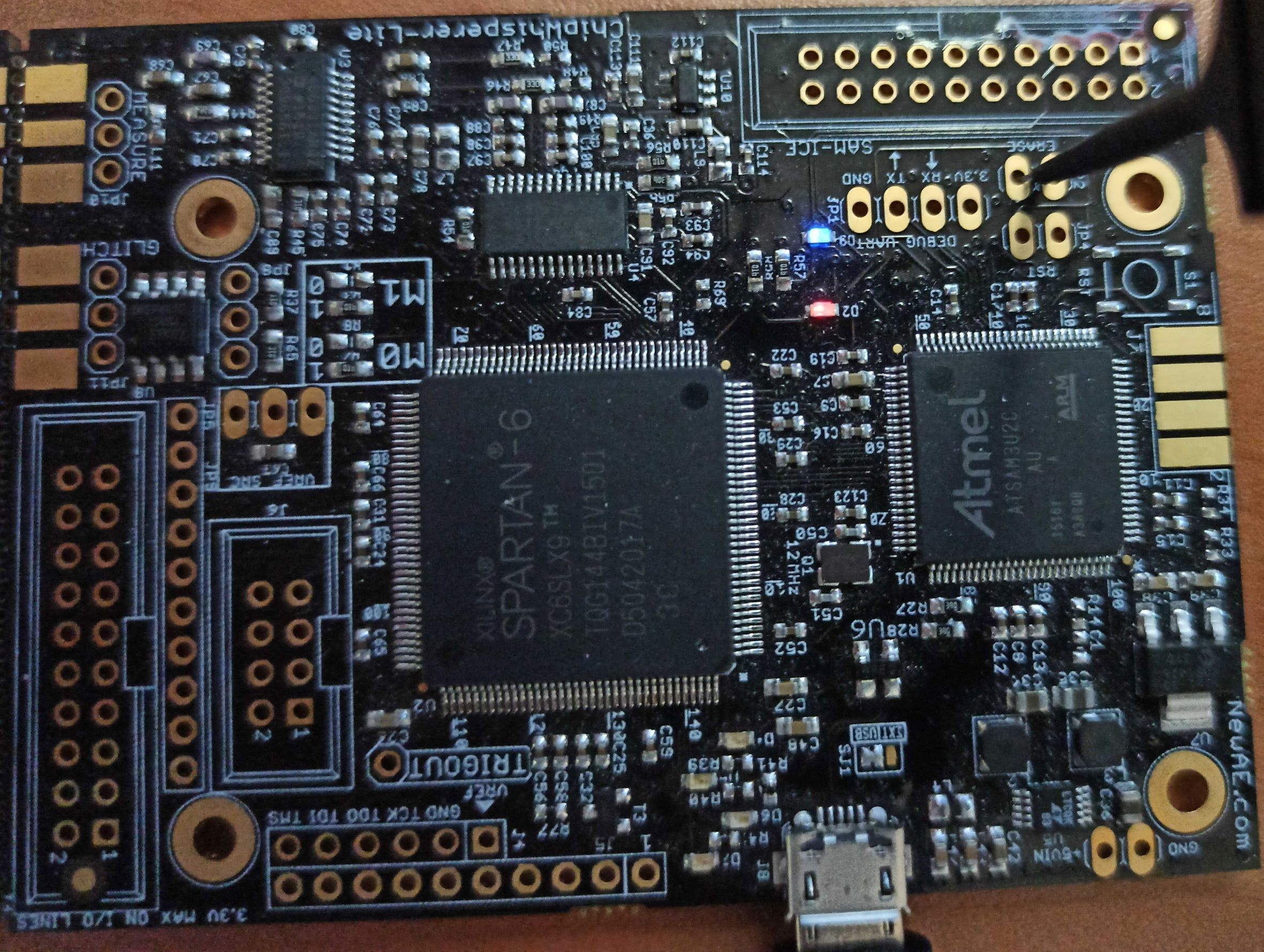
CW1173 ChipWhisperer-Lite
The ChipWhisperer-Lite represents NewAE Technology Inc.’s most aggressive pursuit of it’s mission to bring side-channel power analysis and glitching attacks to every engineer and student. The FULLY open-source (hardware, software, firmware, FPGA code) is launching a revolution in hardware security. In particular, the ChipWhisperer-Lite serves as a good middle ground between the full feature-set of the ChipWhisperer-Pro, and the affordability of the ChipWhisperer-Nano.
The ChipWhisperer-Lite typically comes with two main parts: a multi-purpose power analysis capture instrument, and a target board. The target board is a standard microcontroller which you can implement algorithms onto. For example if you wish to evaluate an AES library, you can program that library into the target board and perform the power analysis.
NOTE: This page will only cover the capture side of the board. See
targets/CW303 for documentation on the target side of the board.

Available in the ChipWhisperer-Lite starter kit, the Level 1 Starter Kit, and the Level 2 Starter Kit
Software Docs/Installation
https://chipwhisperer.readthedocs.io/
Quick-Start Guide
Hardware setup is fast and easy! If you've got a 1-part ChipWhisperer, simply use a micro USB cable to connect the ChipWhisperer-Lite to a computer or laptop. If you've got a 2 part version, you'll also need to connect a 20-pin cable between the ChipWhisperer-Lite and the target, as well as a coax cable between the measure SMA connector (if you're doing power analysis) or the glitch SMA connector (if you're doing voltage glitching) and the SMA connector on the target. For other targets, check the relevant target documentation.
Once that's done, follow our software/driver installation guide at chipwhisperer.readthedocs.io, which will take the rest of the way towards learning about side channel attacks!
Product Highlights
- Synchronous (capture board and target board both use the same clock) capture and glitch architecture, offering vastly improved performance over a typical asynchronous oscilloscope setup
- 10-bit 105MS/s ADC for capturing power traces
- Can be clocked at both the same clock speed as the target and 4 times faster
- +55dB adjustable low noise gain, allowing the Lite to easily measure small signals
- Clock and voltage fault generation via FPGA-based pulse generation
- XMEGA (PDI), AVR (ISP), and STM32F (UART Serial) bootloader built in
Specifications
Analog Capture and Clock
| Feature | Notes/Range |
|---|---|
| ADC Specs | 10-bit 105MS/s |
| ADC Clock Source | Internally generated (x1 or x4 from output clock), external input (x1 or x4 from input clock) |
| Analog Input | AC-Coupled, adjustable low-noise gain from -6.5dB to 55dB |
| Sample Buffer Size | 24 573 samples |
| ADC Decimation | Yes |
| ADC Offset Adjustment | Yes, [0, 2^32) clock cycles |
| ADC Trigger | Rising-edge, Falling-edge, High, Low |
| Presampling | Yes |
| Phase Adjustment | Yes, 5ns increments |
| Capture Streaming | No |
| Clock Generation Range | 5-200MHz |
| Clock Output | Regular, with glitch inserted, glitch only |
Triggering
| Feature | Notes/Range |
|---|---|
| Modules | Basic |
| Analog Trigger | N/A |
| Basic Trigger Inputs | TIO 1-4, nRST |
| Basic Trigger Combination | One of OR, AND, NAND |
IO
| Feature | Notes/Range |
|---|---|
| GPIO Voltage | 3.3V |
| Logic Outputs | TIO 1-4, nRST, PDIC, PDID |
| Logic Inputs | TIO 1-4 |
| UART Serial | TIO 1-4 assignment |
| Clock | Fixed, HS2 output, HS1 Input |
| Trigger Out | No |
| Programmers | STM32F UART, Atmel PDI (for XMEGA), Atmel ISP (for AVR) |
| Power rails | 3.3V |
Glitch
| Feature | Notes/Range |
|---|---|
| Voltage Glitching | Yes |
| Clock Glitching | Yes |
| Glitch Outputs | Clock-XOR, Clock-OR, Glitch-Only, Enable-Only |
| Glitch Width* | 0-49.8% of a clock cycle, 100% (enable-only) |
| Glitch Width Increments | 0.4% of a clock cycle |
| Glitch Offset | 0-49.8% of a clock cycle, 100% (enable-only) |
| Glitch Offset Increments | 0.4% of a clock cycle |
| Glitch Cycle Offset | [0, 2^32) |
| Glitch Cycle Repeat | [0, 8192] |
| Voltage Glitch Type | High-power, low-power crowbar |
| Voltage Glitch Pulse Current | 20A |
| Glitch Trigger | Rising-Edge |
* Actual glitch width will be affected by cabling used for glitch output
USB
| Feature | Notes/Range |
|---|---|
| USB | USB 2.0 High Speed |
| VendorID | 0x2B3E |
| ProductID | 0xACE2 |
| Interfaces | Vendor + CDC (CDC available on firmware >= 0.30) |
| WCID (Windows 10 automatic driver installation) | ✅ (firmware >= 0.22) |
Using the ChipWhisperer-Lite
All communication with the ChipWhisperer-Lite is done through ChipWhisperer's Python API, which is documented on our ReadTheDocs Page.
ChipWhisperer also has many Jupyter Notebook tutorials/labs, which serve as learning material for side-channel
attacks, as well as examples on how to use the ChipWhisperer API. If you followed the install
instructions on ReadTheDocs, this will be in the jupyter/ folder in the place you installed
ChipWhisperer.
We also have full courses available at https://learn.chipwhisperer.io/ that supplement the Jupyter Notebook tutorials.
Using from Other Languages
While the ChipWhisperer API is written in Python, any language that can talk to libusb should be compatable. This will require you to write your own backend and is officially unsupported by NewAE.
Connectors
Using Glitch Port
The "GLITCH" port is used for voltage glitching. It's connected to two MOSFET elements, as the following figure shows:

The CW1173 glitch output can be commanded to turn on either of those
MOSFETs via scope.io.glitch_hp and scope.io.glitch_lp fields:
  scope.io.glitch_hp = True #enable high power glitch
  scope.io.glitch_hp = False #disable high power glitch

  scope.io.glitch_lp = True #enable low power glitch
  scope.io.glitch_lp = False #disable low power glitch
Be careful using this feature, as you don't want to short the MOSFETs for too long. It's also possible to damage the ChipWhisperer-Pro by burning these MOSFETs up if used incorrectly. See Fault101 Voltage Glitch Labs for more information.
Using Measure Port
The "MEASURE" port is the input to the low-noise amplifier and ADC.
20-Pin Connector
The 20-pin connector carries power and IO pins between the ChipWhisperer-Lite and the target board. The pinout is as follows:
| Number | Name | Dir | Description |
|---|---|---|---|
| 1 | +VUSB (5V) | O | Not Connected on ChipWhisperer-Lite. |
| 2 | GND | O | System GND. |
| 3 | +3.3V | O | +3.3V to Target Device, can be turned off, 200mA available. |
| 4 | FPGA-HS1 | I/O | High Speed Input (normally clock in). |
| 5 | PROG-RESET | I/O | Target RESET Pin (nRST). |
| 6 | FPGA-HS2 | I/O | High Speed Output (normally clock or glitch out). |
| 7 | PROG-MISO | I/O | SPI input: MISO (for SPI + AVR Programmer). |
| 8 | VTarget | I | Drive this pin with desired I/O voltage in range 1.5V-5V. |
| 9 | PROG-MOSI | I/O | SPI output: MOSI (for SPI + AVR Programmer). |
| 10 | FPGA-TARG1 | I/O | TargetIO Pin 1 - Usually UART TX or RX. |
| 11 | PROG-SCK | I/O | SPI output: SCK (for SPI + AVR Programmer). |
| 12 | FPGA-TARG2 | I/O | TargetIO Pin 2 - Usually UART RX or TX. |
| 13 | PROG-PDIC | I/O | PDI Programming Clock (XMEGA Programmer), or CS pin (SPI). Also used for STM32 bootloader |
| 14 | FPGA-TARG3 | I/O | TargetIO Pin 3 - Usually bidirectional IO for smartcard. |
| 15 | PROG-PDID | I/O | PDI Programming Data (XMEGA Programmer). |
| 16 | FPGA-TARG4 | I/O | TargetIO Pin 4 - Usually trigger input. |
| 17 | GND | O | |
| 18 | +3.3V | O | |
| 19 | GND | O | |
| 20 | +VUSB (5V) | O | Not Connected on ChipWhisperer-Lite. |
Advanced Usage
Serial Port
Beginning with firmware 0.30 (released with ChipWhisperer 5.5), the ChipWhisperer-Lite enumerates as both a custom USB device, as with previous firmware, as well as a USB CDC serial port.
This new serial port allows you to use a serial client, such as Tera Term or PuTTY, to send and receive USART data on the ChipWhisperer in the same way target module is normally used. These two USART methods can be used individually, or both at the same time, though we recommend that you don't send messages on both at the same time.
For more information, please read our serial port rtfm page
This new serial port has a few advantages:
- Periodic polling by the OS means dropped RX data should be rare
- The RX buffer on the OS means reading serial data costs almost no program time
- With the cw target module, reading serial data, for example, slows down a capture loop
- Can send/receive serial data using either Python, or a serial client (though not both at the same time)
As well as a few disadvantages:
- Need to keep track of a serial port (/dev/ttyACMX or COMX) if not using pyserial
- In addition, old versions of PySerial don't allow us to associate
Mounting Jumpers
The ChipWhisperer-Lite main board and target section contain a number of jumper options. By default these are not mounted, and solder jumper bridges on the PCB have been bridged to select the appropriate options when required. Some options are only solder jumpers, requiring a soldering iron to bridge or clear the appropriate connections.
The following lists jumpers on the ChipWhisperer-Lite Capture Section:
-
JP4 is the "RESET" net for the SAM3U processor.
-
JP2 causes the SAM3U processor flash memory to be erased. When the chip is erased a rom-resident bootloader takes over. See section XXXXX for bootloader details.
- JP5 selects the IO voltage for the FPGA bank which connects to the 20-pin target. By default SJ6 selects this to be 3.3V. It is not recommended to change this, as it is easy to damage the FPGA by feeding an out-of-range voltage in.
- SJ1 selects if the power supply comes from the Micro-USB connector (default) or an external 5V supply at the +5VIN pin.
Breaking Target Section Apart
You may wish to break the target section apart from the main capture board. This can easily be accomplished by following these instructions:
- Using a sharp knife (such as Xacto knife or retractable safety knife), cut the traces on the bottom side of the board along the cut line. Pass the knife back and forth several times. Scoring the board deeply will make the breaking process easier and less stressful on the PCB:

- Score the board on the top side:

- Select a surface to break the board over. It is suggested to have a piece of cardboard or boxboard down to protect components on the bottom side of the ChipWhisperer:

- Hold the main board section flat, apply even pressure to the target board section. It should snap downward:

- Separate the two sections:

You can see a video of the process here:
Applying even pressure will help prevent damage to the ChipWhisperer-Lite main section. Flexing the PCB too much may cause damage to solder joints, but by holding the entire board flat against the edge this is prevented.
Upgrading SAM3U Firmware
When talking about the ChipWhisperer's firmware, there is really two parts to this:
- The FPGA Bitstream file.
- The SAM3U USB interface chip firmware.
The FPGA bitstream alone is what is normally configured by the ChipWhisperer-Capture software. This bitstream is always the most up-to-date, since it's automatically reloaded by the computer every time you power cycle the ChipWhisperer-Capture. The SAM3U firmware is not updated automatically, but it tends to change less frequently.
Checking Firmware Version
The firmware version can be accessed as follows:
>>> import chipwhisperer as cw
>>> scope = cw.scope()
>>> print(scope.fw_version)
{'major': 0, 'minor': 11, 'debug': 0}
The version of the newest firmware can be printed as follows:
>>> import chipwhisperer as cw
>>> scope = cw.scope()
>>> print(scope.latest_fw)
{'major': 0, 'minor': 11}
If a firmware update is available, the user will be warned when connecting to the scope:
>>> scope = cw.scope()
WARNING:root:Your firmware is outdated - latest is 0.12. Suggested to update firmware, as you may experience errors
See https://chipwhisperer.readthedocs.io/en/latest/firmware.html
Upgrading Firmware
See https://chipwhisperer.readthedocs.io/en/latest/firmware.html for instructions on how to update the SAM3U firmware.
Erase Pins
If you are unable to connect to the ChipWhisperer-Lite to erase its firmware, the SAM3U firmware
can also be erased by shorting JP2 while the Lite is on. With the USB connector
above, JP2 is located below the SAM3U, directly above the
20-pin connector on the bottom left of the board and has the text ERASE below
it.
After shorting the pins, unplug and replug the USB connector and you should see D2 and D9 lit dimly, indicating that the firmware has been erased.
Linux usbserial module Workaround
There is an issue in some versions of Linux, where the SAM3U is not assigned a serial port when it enters bootloader mode. Here are some steps to resolve this issue (Note. this is not a permanent fix, you must go through these steps each time you put your ChipWhisperer into bootloader mode.). These steps assume you've already put ChipWhisperer into bootloader mode.
- Unplug your ChipWhisperer (Leave unplugged until instructed otherwise)
- Reboot your computer
- Once logged in again, open a terminal session
- Run this command:
sudo modprobe usbserial vendor=0x3eb product=0x6124 - Plug your ChipWhisperer back in
- Check that a serial port is now open using:
ls -l /dev/ttyUSB*

You should now be able to program the bootloader from ChipWhisperer Capture through the port you created
Generating Partial Reconfig Files
The Lite uses partial reconfiguration to adjust the phase offset for glitch width/offset.
If you're doing a custom bitstream and want to generate these files, it can be done as follows:
- Get the .bit file built (from directory hardware/capture/chipwhisperer-lite/hdl, you'd run the commands in makeprojects_win.bat, then open the project in ISE & build the bitstream)
- Run the script generate_reconfig_dicts.py in that same directory. This script takes a LONG time to run, as it generates bitstreams for each option.
- Afterwards you'll get two files - cwlite-glitchoffset.p & cwlite-glitchwidth.p . You must copy these two files + the file cwlite_interface.bit that you built in step 1 into a zip-file, called cwlite_firmware.zip.
- Make a backup of
chipwhisperer/hardware/capture/chipwhisperer-lite/cwlite_firmware.zipandchipwhisperer/software/chipwhisperer/hardware/firmware/ - Replace
chipwhisperer/hardware/capture/chipwhisperer-lite/cwlite_firmware.zipwith this new file. - Open
chipwhisperer/software/chipwhisperer/hardware/firmware/generate_firmware_files.pyand, withinfile_list, comment out every entry except the one containingcwlite.py. After this, rungenerate_firmware_files.py.
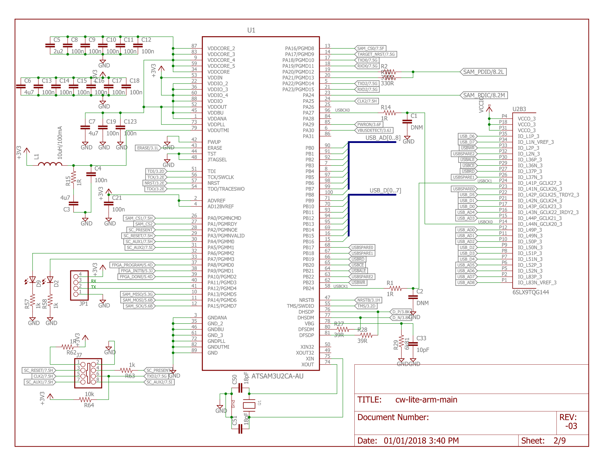
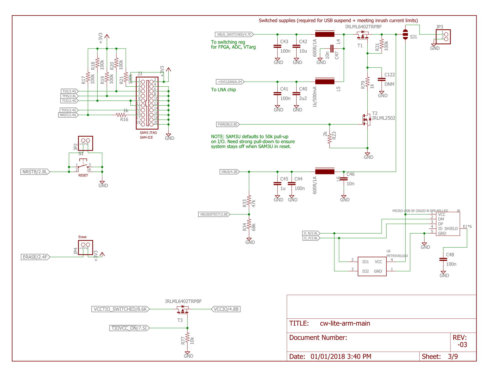
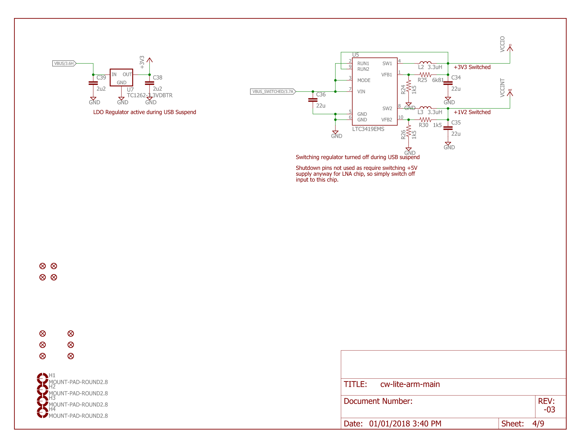
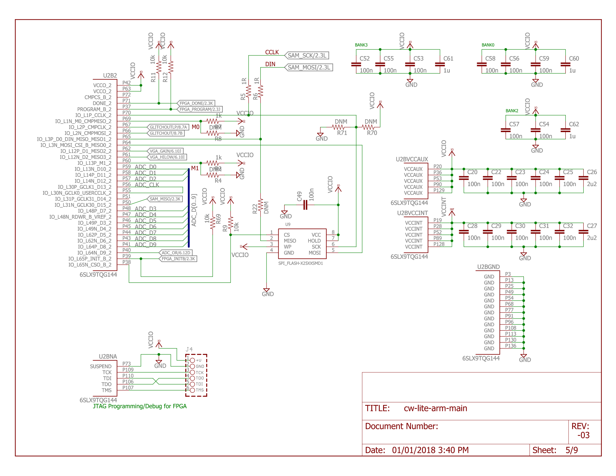
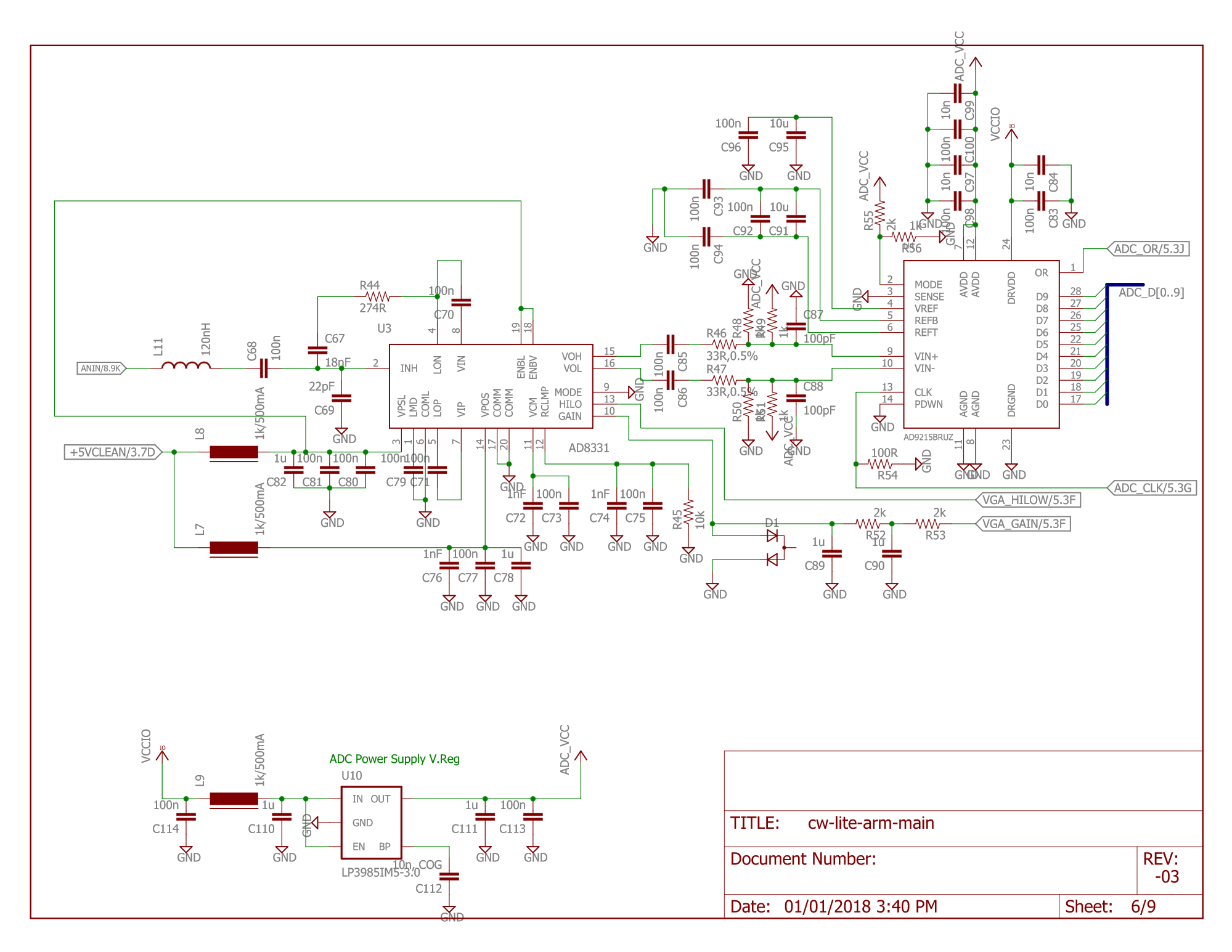
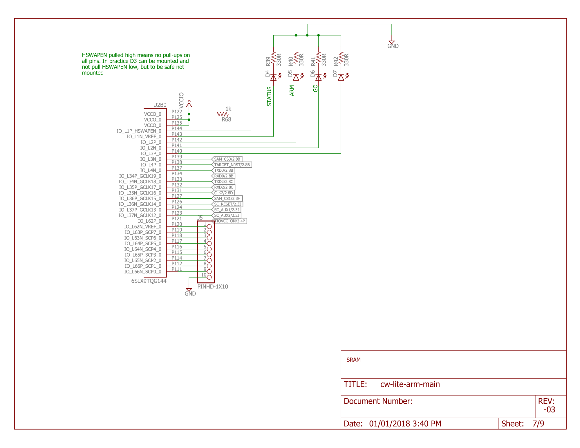
Schematic

Errata
VCC Transistors Get Stuck on During Glitching
When voltage glitching, the glitch transistor in use can get stuck on. This keeps the
target's VCC rail pulled low until the transistor is deactivated via scope.io.glitch_lp or scope.io.glitch_hp.
Workaround
Toggle scope.io.glitch_lp/scope.io.glitch_hp after each glitch attempt. scope.io.vglitch_reset() can be called
to do this.
offset_fine and width_fine are write-only
scope.glitch.offset_fine and scope.glitch.width_fine are write-only and reads will always return 0.
Workaround
Store values written to these properties separately.